Do you have a question about the VEVOR TLGS825 and is the answer not in the manual?
Ensures electrical safety by providing a path for current to reduce shock risk.
Instructions for carefully inspecting the machine and its parts upon arrival.
Guidance on securely attaching the grinder to a workbench.
Steps to install the safety shield for eye protection during grinding.
Steps to attach the tool rest for grinding and work stop for belt sanding.
Procedure to adjust the sanding belt to ride on the center of the rollers.
How to tilt the sanding arm from horizontal to vertical position.
Steps for initial operation and checks after assembly.
Procedure for checking the grinding wheel for damage before installation.
Instructions for safely removing and installing a new grinding wheel.
Steps to remove and install a new sanding belt.
Routine checks and cleaning to maintain machine performance.
Diagram showing the assembly of machine components with part numbers.
Detailed list of all machine parts with specifications and quantities.
This document outlines the operation, features, and maintenance of a Grinder and Belt Sander Combo. This versatile machine is designed for both grinding and belt sanding tasks, offering a professional tool for various applications. Adhering to the instructions and safety procedures detailed in this manual will ensure years of excellent service and satisfaction.
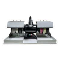
The Grinder and Belt Sander Combo is a dual-purpose power tool that integrates a grinding wheel and a belt sanding mechanism into a single unit. The grinding wheel is primarily used for sharpening, shaping, and removing material from metal workpieces. The belt sander, on the other hand, is ideal for smoothing, finishing, and deburring a variety of materials, including wood and metal. The machine is equipped with a motor that drives both the grinding wheel and the sanding belt, allowing for efficient and precise material removal. The design includes various adjustable components to accommodate different workpieces and tasks, enhancing its utility in a workshop environment.
The machine incorporates several features to facilitate its use and enhance operator safety. Proper grounding is crucial for safe operation, and the manual provides clear instructions on how to connect the machine to a properly installed and grounded power outlet. It is strongly recommended to avoid using extension cords, but if necessary, specific guidelines are provided to prevent motor damage.
Before operation, the machine requires unpacking and mounting. The unit is shipped in a carton and should be carefully inspected for any damage during transit. The machine weighs 38 lbs and must be mounted on a workbench capable of supporting its weight, with the surface being level. Two pre-drilled holes on the base allow for secure mounting using bolts (not provided).
An eye safety shield is provided to protect the operator's face from sparks produced during grinding. This shield should be positioned 1/8” from the grinding wheel and securely attached using the provided screws and washer.
Tool rests and a work stop are integral to the machine's functionality, providing support for workpieces during grinding and belt sanding operations. These components should be attached to the grinder so that they are perpendicular to the belt and grinding wheel. The tool rests should be adjusted to be 1/8" to 1/16” away from the belt and wheel before tightening the screws.
Belt tracking is another critical feature that ensures the sanding belt rides on the center of the rollers and does not come into contact with the side covers. This adjustment is made by turning the belt tracking adjustment knob while manually rotating the grinding wheel.
The machine also features a 1-1/8" dust port located under the rollers. When connecting to a dust collector, a proper sized hose should be used, and all connections must be tightly sealed to manage dust produced during operation.
The sanding arm angle is adjustable, allowing it to be tilted through 90° from a horizontal to a vertical position. This flexibility enables the machine to handle various sanding tasks and workpiece orientations. To adjust the sanding arm, the switch must be turned OFF, the two screws loosened, the arm moved to the desired position, and the screws retightened.
A test run is recommended after assembly to ensure the machine powers up and runs properly, with the grinding wheel secured, the belt tensioned, and tracking correctly. All tools and objects used for assembly should be removed before the test run. During the test run, the start/stop button and all safety features should be checked for proper functioning. Any unusual noise or vibration should prompt immediate disconnection from the power source and a thorough inspection of all assembled parts.
Regular maintenance is essential to keep the machine in peak performance condition throughout its life. Routinely checking for damaged or loose grinding wheels, worn power cords, worn switches, and any loose hardware is crucial.
The grinding wheel, which comes as an 8" diameter, A60 grit aluminum oxide wheel, should be inspected properly before installation and regularly thereafter for any internal or external damages such as cracks, dents, or chips. An internal inspection involves holding the wheel with a finger through the center hole and tapping it with a wooden mallet or a light non-metallic object. A clear sound indicates a good wheel, while a dull sound may suggest internal damage. Tapping with heavy or metallic objects can damage the wheel.
Grinding wheel replacement involves ensuring the switch is OFF and the cord is disconnected. The wheel guard needs to be removed by loosening three screws to expose the wheel. The nut securing the grinding wheel is then loosened while holding the wheel with one hand. After removing the nut, washer, and old wheel, a new, properly inspected grinding wheel can be installed.
Sanding belt replacement also requires the switch to be OFF and the cord disconnected. The belt guard is removed by unscrewing the knob securing the belt cover. The belt tension lever is then moved up to loosen the tension on the belt, allowing the old belt to be taken off the rollers and replaced with a new one. After installing the new belt, the tension lever is moved down to tension the belt, the belt cover is reinstalled, and belt tracking adjustment is performed as detailed in the usage features.
The bearings in the machine are pre-lubricated and do not require additional lubrication. Wood dust from the sanding belt can be cleaned by using an abrasive cleaner against the sanding belt while the machine is moving.
It is critical to always turn the switch OFF and unplug the cord from the power source before installing, servicing, or making any adjustments to prevent serious personal injury.
| Type | Belt Sander |
|---|---|
| Dust Extraction | Yes |
| Weight | 6.6 lbs |
| Power Source | Electric |
| Belt Size | 3 x 18 inches |