EasyManua.ls Logo

Vex CORTEX User Manual

Vex CORTEX
9 pages
To Next Page IconTo Next Page
Page #1 background imageLoading...
Page #1 background image
CORTEX Microcontroller and Joystick Quick Start Guide
Page 1 of 9
This is a Quick Start Guide for using the VEX CORTEX Microcontroller and VEX Joystick. Refer to the VEX Wiki
(http://www.vexforum.com/wiki/index.php/VEX_Cortex_Microcontroller) for updates to this document.
1. Basic connections; batteries, microcontroller, joysticks and (2) VEXnet keys.
a. Attach 7.2v battery power and a VEXnet 802.11g key to the VEX CORTEX as shown.
b. Add AAA batteries to the Joystick by loosening the screw as shown. Remove the battery cover.
c. Install six identical batteries as shown. Use Alkaline, Ni-Cad or Ni-MH chemistries, but DO NOT mix different
chemistry batteries. Charge rechargeable batteries only with a quality charger designed for your battery chemistry.
0510
Question and Answer IconNeed help?

Do you have a question about the Vex CORTEX and is the answer not in the manual?

Vex CORTEX Specifications

General IconGeneral
Digital I/O Pins16
Battery7.2V
TypeMicrocontroller
Input Voltage7.2V
Analog Inputs8
Wireless CommunicationVEXnet 1.0

Summary

Basic Connections and Setup

Attaching Power and VEXnet Key

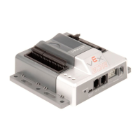
Attach 7.2v battery power and VEXnet 802.11g key to the CORTEX.

Joystick Battery Installation

Add AAA batteries to the Joystick by loosening the screw and removing the cover.

Battery Chemistry Guidelines

Install six identical batteries; do not mix chemistries. Charge rechargeables properly.

Basic Configuration

Connecting Motors and Testing

Connect motors to ports and test response to joystick input.

Motor Reversing Configuration

Use jumpers in Digital Ports to invert motor direction.

Analog Input Information

Analog Circuit Details

Describes analog input range, pull-up, resistors, and capacitor.

Digital Input/Output Information

Digital Port Circuit Details

Details digital input range, drive, resistors, and capacitor.

SP Digital Port Circuit Details

Describes SP digital port connection to DAC and its limitations.

Technical Specifications and Debugging

2-Wire and 3-Wire Motor Port Outputs

Details maximum stall current and overcurrent protection for motor ports.

UART and I2C Connection Details

Specifies connection parameters for UART and I2C.

Joystick Calibration and Debugging

Covers optional calibration and common troubleshooting steps for LEDs and functionality.