CORTEX Microcontroller and Joystick Quick Start Guide
Page 3 of 9
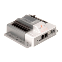
g. A valid link is as shown. The VEXnet light will be blinking a fast green on both units. The Robot light will wink green
(be mostly on) on both units and when using fully charged batteries. It will take about 10 to 15 seconds for a link to
be established. The Joystick light will be solid green when using fully charged batteries.
h. If the units fail to link up, turn them both OFF and back ON. If they still fail to link up, tethering may be required.
Refer to the Tethering document for tethering instructions.
2. Basic Conguration
A few examples of the Default Code that is pre-programmed into the Cortex Microcontroller are shown below. For
complete details on the Default Code, refer to Section 3.
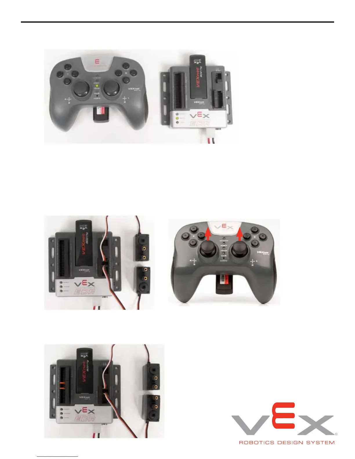
a. Add motors and test. The following picture shows 276-2163 VEX Motors plugged into Motor Port 2 and Motor Port
5. With default code, pushing Joystick Channel 3 up will cause Motor 2 to turn clockwise. Pushing Joystick Channel
2 up will cause Motor 5 to turn counterclockwise.
b. Motor Reversing: The default code allows jumpers or switches to be installed in the Digital Ports to invert the motor
direction. This is useful to correct the direction of motors without changing code, or when using a switch to reverse a
motor if the robot hits an object. The following picture shows motor reversing jumpers installed in Digital Ports 2 and
5 to reverse Motor Ports 2 and 5.
3 2
 Loading...