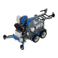
The VEX EDR Speed Build is a robot designed for quick assembly and versatile operation, capable of both autonomous control and manual operation via the V5 Controller. This manual provides comprehensive instructions for building the robot and details the necessary components.
Function Description:
The VEX EDR Speed Build serves as a foundational robot platform within the VEX EDR ecosystem. Its primary function is to provide an accessible and rapid construction experience, allowing users to quickly assemble a functional robot for educational, competitive, or experimental purposes. The design emphasizes ease of assembly, making it suitable for beginners while still offering the robust capabilities of the VEX EDR system. Once built, the robot can be driven in two primary modes: autonomously, where it executes pre-programmed instructions, or manually, using the V5 Controller for real-time command. This dual functionality makes it a versatile tool for learning about robotics, programming, and mechanical design. The robot's chassis is constructed from VEX U-Channels and Angle pieces, forming a sturdy and adaptable base for various attachments and modifications. The drive system utilizes V5 Smart Motors, which provide precise control and feedback, essential for both autonomous navigation and responsive manual driving. The inclusion of both 4-inch wheels and 4-inch Omni Wheels suggests potential for different drive configurations, allowing for varied maneuverability characteristics. The V5 Robot Brain acts as the central processing unit, managing motor control, sensor input, and communication with the V5 Controller and V5 Radio. The V5 Battery provides power to the entire system, ensuring sustained operation. The design also incorporates various fasteners and spacers to ensure structural integrity and proper component alignment.
Important Technical Specifications:
Chassis Components:
- U-Channels: 3x - 2x2x2x20 U-Channel. These form the main structural beams of the chassis, providing rigidity and mounting points.
- Angles: 2x - Angle 2x2x14x20. Used for connecting chassis components at right angles, enhancing structural stability.
Drive System Components:
- Smart Motors: 2x - V5 Smart Motor. These are intelligent motors that provide power to the wheels and offer integrated encoders for precise control.
- Shafts:
- 2x - 3 in Shaft. Used for connecting wheels to motors or other drive components.
- 2x - 4 in Shaft. Provides longer reach for wheel mounting or other mechanisms.
- Wheels:
- 2x - 4 in Wheel. Standard wheels for general mobility.
- 2x - 4 in Omni Wheel. Allows for holonomic movement (sideways motion) when used in specific drive configurations.
- Shaft Inserts: 8x - High Strength Shaft Insert. Used to secure shafts within components, preventing slippage and ensuring smooth rotation.
- Rubber Shaft Collars: 12x - Rubber Shaft Collar. Used to secure shafts in place and prevent axial movement.
- Bearing Flats: 4x - Bearing Flat. Provides low-friction support for rotating shafts.
Electronics:
- Robot Brain: 1x - V5 Robot Brain. The central controller for the robot, processing code and managing all electronic components.
- Radio: 1x - V5 Radio. Enables wireless communication between the V5 Robot Brain and the V5 Controller.
- Battery: 1x - V5 Battery. Provides power to the V5 Robot Brain and all connected components.
- Battery Cable: 1x - V5 Battery Cable. Connects the V5 Battery to the V5 Robot Brain.
- Smart Cables: 3x - 300mm V5 Smart Cable. Used to connect V5 Smart Motors and other V5 Smart Devices to the V5 Robot Brain.
- Battery Clips: 2x - V5 Battery Clip. Secures the V5 Battery to the robot chassis.
- Connector Pins: 4x - 0x2 Connector Pin. Used for connecting various electronic components or sensors.
Fasteners and Spacers:
- Nuts: 14x - 8-32 Nut. Standard nuts for securing screws.
- Screws:
- 16x - 8-32 x 0.375 in Screw. Short screws for general fastening.
- 2x - 8-32 x 0.5 in Locking Screw. Slightly longer screws, potentially with a locking feature to prevent loosening.
- 2x - 8-32 x 1.5 in Locking Screw. Longest screws, likely for securing components through multiple layers or with spacers.
- Spacers:
- 4x - 0.375 in Spacer. Used to create distance between components.
- 2x - 0.5 in Spacer. Provides a larger separation distance.
- Hex Nut Retainers:
- 4x - 1 Post Hex Nut Retainer w/ Bearing Flat. Combines a nut retainer with a bearing flat, simplifying assembly.
- 6x - 4 Post Hex Nut Retainer. Holds multiple nuts in place, useful for securing larger components.
Usage Features:
The VEX EDR Speed Build is designed with several user-friendly features to enhance the building and operating experience:
- Quick Build Design: The robot's structure and component selection are optimized for rapid assembly, allowing users to get a functional robot up and running in a short amount of time. This is particularly beneficial in educational settings or for quick prototyping.
- Autonomous Operation: The V5 Robot Brain allows for programming autonomous behaviors, enabling the robot to perform tasks without direct human intervention. This feature is crucial for learning programming concepts and preparing for robotics competitions.
- V5 Controller Compatibility: The robot can be easily controlled manually using the V5 Controller, providing an intuitive and responsive driving experience. The V5 Radio facilitates seamless wireless communication between the controller and the robot.
- Modular Design: The VEX EDR system is inherently modular, meaning components can be easily added, removed, or rearranged. This allows for customization and expansion of the Speed Build robot to perform different functions or adapt to various challenges.
- Clear Build Instructions: The manual provides step-by-step visual instructions, making the assembly process straightforward even for novice builders. Each step clearly lists the required components and shows the expected outcome.
- Instructional Tips: The "Build Instruction Tips" section offers valuable advice, such as checking for proper motor orientation, understanding when to flip the build, and correctly connecting V5 Smart Cables to the Robot Brain. These tips help prevent common errors and ensure successful assembly.
- Component Identification: Each step clearly identifies the components needed, often with images, reducing ambiguity during the build process.
- Sub-Assembly Integration: The instructions guide the user through creating sub-assemblies that are then integrated into the main robot, breaking down complex tasks into manageable steps.
Maintenance Features:
While the manual does not explicitly detail a "maintenance features" section, the VEX EDR system's design inherently supports ease of maintenance:
- Standardized Components: The use of standardized VEX EDR components means that spare parts are readily available and interchangeable, simplifying repairs and replacements.
- Robust Fastening System: The reliance on 8-32 nuts and screws, along with hex nut retainers, provides a secure fastening system that can be easily tightened or loosened with standard VEX tools. This allows for easy access to internal components for inspection or repair.
- Modular Electronics: The V5 Robot Brain, Smart Motors, Radio, and Battery are all distinct modules connected by V5 Smart Cables. This modularity simplifies troubleshooting, as individual components can be easily disconnected and tested or replaced if faulty.
- Durable Materials: VEX EDR components are generally made from durable plastics and metals, designed to withstand the rigors of repeated assembly, disassembly, and operation.
- Accessible Design: The open chassis design allows for relatively easy access to motors, shafts, and wiring, facilitating inspection, cleaning, and adjustments.
- Bearing Flats and Shaft Collars: These components are designed to reduce friction and secure shafts, contributing to the longevity and smooth operation of the drive system. Regular inspection of these parts can help identify wear and tear before it leads to performance issues.
- Cable Management: While not explicitly detailed, the design allows for organized cable routing, which is crucial for preventing damage to wires and ensuring reliable electrical connections. Proper cable management contributes to the overall maintainability of the robot.