www.fmiproducts.com
108919-01H 7
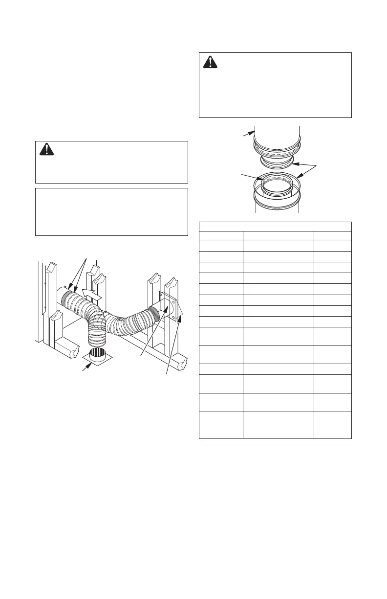
Figure 8 - Lineal Gain
LINEAL GAIN
PART NO. DESCRIPTION GAIN
42" Fireplace 37
1
/
2
"
12-8DM Pipe Section 10
5
/
8
"
18-8DM Pipe Section 16
5
/
8
"
24-8DM Pipe Section 23
5
/
8
"
36-8DM Pipe Section 34
5
/
8
"
48-8DM Pipe Section 46
5
/
8
"
RT-8DM Round Termination 6
7
/
8
"*
RTL-8DM Round Termination 7
3
/
4
"*
RTT-8DM
Round Termination
with Slip Section
6
7
/
8
" to
23
1
/
8
"*
RTTL-8DM
Round Termination
with Slip Section
8
1
/
2
" to
21
1
/
2
"*
ET-8DM Square Chase-Top 12"*
ETO-8DM
Square Chase-Top
with Mesh
12"*
ETL-8DM
Square Chase-Top
with Slip Section
7" to 15"*
ETLO-8DM
Square Chase-Top
with Mesh & Slip
Section
12" to
25
1
/
2
"*
* The lineal gain for the terminations is
measured to the flue gas outlet height.
Hemmed
End
8" Stainless
Inner Pipe
12
3
/
8
"
Galvanized
Outer Pipe
Figure 7 - Outside Air Kit
Secure to Collars with Metal Tape, Screws
or Straps (Min. of 1/4" x 20" in size)
Air Inlet
Location
Must Allow
For Bushes
or Snow
Vent Hood
Required for
Wall Installation
Air Inlet
Eyebrow
Vented Crawl Space
(Check Local Codes
Before Installing in a
Vented Crawl Space)
VENTING INSTALLATION
OPTIONAL OUTSIDE AIR KIT
(MODEL AK4/AK4F)
Installation of outside air kit should be per-
formed during rough framing of fireplace due
to the nature of it's location. Outside combus-
tion air is accessed through a vented crawl
space (AK4F) or through a sidewall (AK4).
See Figure 24 on page 15 for instruction of
operating air kit.
CAUTION: Combustion air
inlet ducts shall not terminate
in attic space.
The maximum height for the
air vent can not exceed 3 feet
below the flue gas outlet of the
termination.
CHIMNEY PIPE
Style Crest, Inc chimney system consists of
12", 18", 24", 36" and 48" snap-lock, double-
wall pipe segments, planned for maximum
adaptability to individual site requirements.
Actual lengths gained after fitting overlaps
must be taken into consideration (lineal
gain) and are given in lineal gain chart (see
Figure 8).
Lineal gain is actual measurable length of a
part after two or more parts are connected.
WARNING: The opening in
collar around chimney at top of
fireplace must not be obstructed.
Never use blown insulation to fill
chimney enclosure.