S.S.
S.D.
SPEED
FG
N.C.
N
L
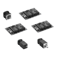
BRUSHLESS DC MOTOR
DRIVER FBLD120AW
VEXTA
1
2
3
4
5
6
7
8
9
10
11
12
1
2
3
4
5
6
7
8
9
10
11
12
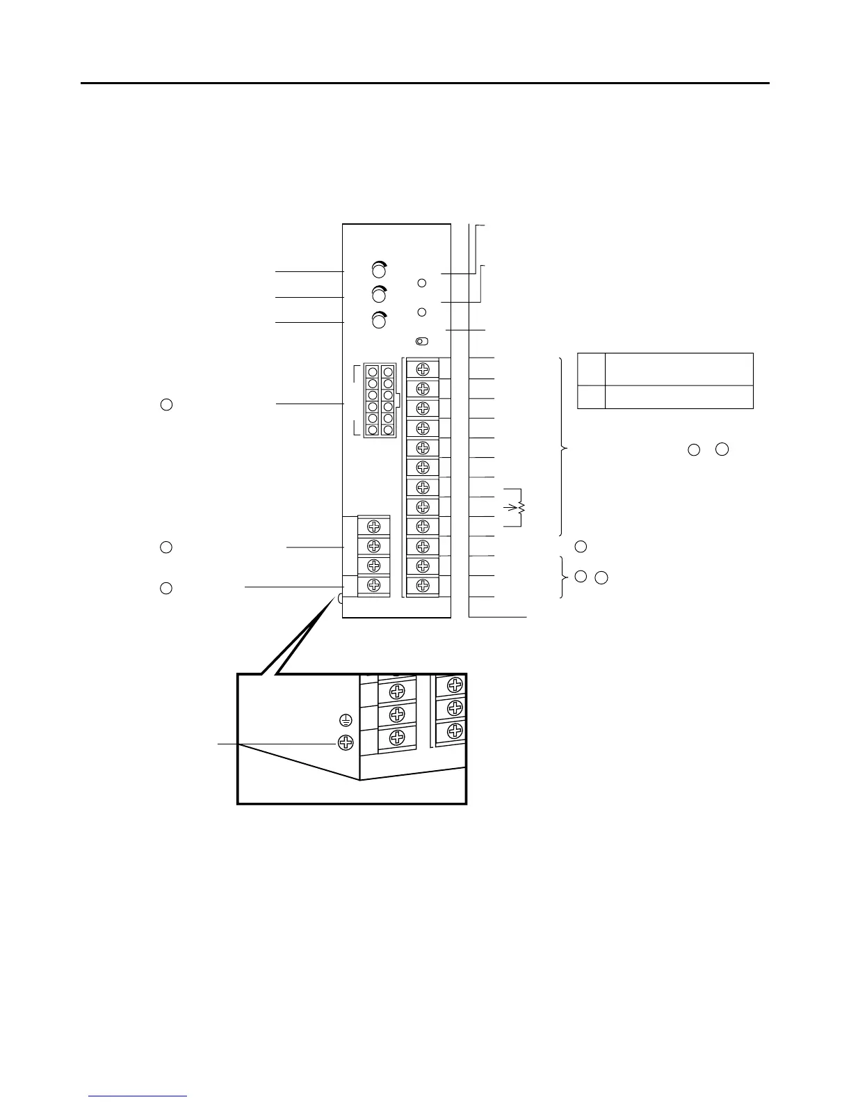
INPUT COM
EXT.VR.
CW
CCW
SLOW DOWN
N.C.
H
M
L
GND
SPEED OUT
ALARM OUT
I/O
Power Indicator(Green)
Power Indicator
lights when power is on
Acceleration time potentiometer
Deceleration time potentiometer
Internal speed potentiometer
I/O power supply switch
Alarm Indicator (Red)
Alarm Indicator
Indicates that an alarm signal has been
output when either the overload, overvoltage
overheating or out-of-phase protection
function is activated.
16For motor connector
13Power supply terminals
14Frame ground
EXT.
Set at time of shipment.
When controlling from a programmable
controller or other external power supplt.
INT.
When controlling with a relay or switch.
Input signal terminals(1〜9)
11,12Output signal terminals
10 Ground for input/output signals
※See page 14 for details.
POWER
ALARM
EXT.–INT.
MOTOR
Driver Front panel The right side of Driver
 Loading...