Do you have a question about the Vi.Be.Mac 3022 Series and is the answer not in the manual?
Details on the machine's electrical supply voltage and compressed air needs.
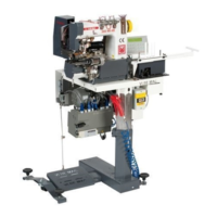
Specifications for machine size, weight, and optimal workspace setup.
Details on the warranty period, coverage, exclusions, and manufacturer's liability.
Instructions for operating the main power switch for the unit.
Description of the power switch for the LS01/M control panel.
Explanation of the control board's role in monitoring the automatic unit's operation.
Guide to operating the air cocks for the pneumatic system.
Procedure for powering on and preparing the sewing machine for operation.
Procedure for safely powering down the sewing machine.
Information on setting the servomotor's direction of rotation.
Steps for starting Program 3 with trouser material insertion.
Steps for completing Program 3 at the end of trouser processing.
Steps for starting Program 4 with trouser material insertion.
Steps for completing Program 4 at the end of trouser processing.
Layout and function of the LS01/PMG panel's numerical and function keys.
Procedure for turning on the machine and understanding panel display states.
Instructions for activating and deactivating the LS01/PMG control panel.
Explanation of the primary operational modes and display messages.
Steps to select and load a different sewing program onto the panel.
Guidance on setting up sequential execution of multiple sewing programs.
How to activate or deactivate specific machine functions via the panel.
Procedure to reset the current program or sequence back to the start.
Detailed guide to configuring counters for program 3 operations.
Setting the unstitching length for material insertion in Program 3.
Setting the unstitching length for presser foot lowering in Program 3.
Setting the start point for the final unstitching sequence in Program 3.
Configuring the length of the final unstitching operation in Program 3.
Setting the counter for the initial cutting operation in Program 3.
Setting the counter for the final cutting operation in Program 3.
Setting the delay count for the pincer function in Program 3.
Detailed guide to configuring counters for program 4 operations.
Setting the unstitching length for material insertion in Program 4.
Setting the unstitching length for presser foot lowering in Program 4.
Setting the start point for the final unstitching sequence in Program 4.
Configuring the length of the final unstitching operation in Program 4.
Setting the counter for the initial cutting operation in Program 4.
Setting the counter for the final cutting operation in Program 4.
Setting fundamental parameters and functions for the machine's operation.
Method for directly setting stitch resolution parameters.
Testing the input signals from photocells and detectors.
Testing input signals originating from the motor panel.
Testing input signals to the machine's electrovalves.
Testing functions related to automatic speed adjustment and motor stopping.
Details on the machine's available automatic speed settings.
Procedure for safely exiting the machine's test mode.
Details on the positioner's role and adjustment for needle stop.
Introduction to the FMFY control panel features and layout.
Configuring the needle's stopping point at the end of the sewing cycle.
Adjusting the sewing head's speed percentage.
Configuring maximum sewing speed, positioning, and cutting parameters.
Adjusting impulses for step motor control to set stitch length.
Performing diagnostic tests on machine inputs and outputs.
Saving the machine's programming into the memory panel.
Steps to clear and reset the panel's memory.
Troubleshooting guide for error messages displayed on the panel.
Reference table for machine parameters and their settings.
Description of the three photocells used for positioning and signaling.
Details on the safety sensor located near the puller.
Adjusting photocell position, inclination, and sensitivity for optimal performance.
Details on the electrovalve controlling the cutting function.
Details on the electrovalve controlling the unstitching function.
Details on the electrovalve controlling the pincer group.
Details on the electrovalve for safety cylinder control.
Details on the electrovalve for lifting the presser foot.
Details on the electrovalve for needle cooling.
Description of the micro switch preventing cutting when the cover is removed.
Description and function of the cylinder for the cutting device.
Description of the cylinder for safety cutting operations.
Details on the double-acting cylinder for lifting the presser foot.
Description of the special double-acting cylinder for pulling material.
Details on the single-acting cylinder for the unstitching function.
Guide to adjusting the position and changing the upper puller roller.
Explanation of the variable pulley for adjusting upper roller speed.
Details on the lower roller's role in material transport and stitch length.
Steps for correctly positioning and aligning the folder mechanism.
Adjusting worktable height and ensuring folder parallelism.
Adjusting the border holder inclination for waistband formation.
Description of the band guide's role in waistband preparation.
Guide to adjusting the presser foot pressure for optimal sewing.
Adjusting the position of the movable knife in the cutting device.
Adjusting the cutting pressure for the movable knife.
Procedure for changing the upper and lower knives of the cutting device.
Adjusting the unstitching latten for correct comb and needle alignment.
Adjusting the support for the unstitching cylinder's slide.
Procedure for setting the correct height of the needle bar.
Correctly positioning the needle plate relative to the needle.
Setting the position and height of the guiding slit needle plate.
Eccentric mechanism for synchronizing needle bar translation with material.
Setting the pendulum position of the needle bar for stitch quality.
Eccentric for synchronizing looper movement with needle bar descent.
Adjusting the precise distance between the looper and the needle.
Eccentric for synchronizing spreader movement with needle and looper.
Modifying stitch length by adjusting step motor impulses.
Adjusting the plugs on the lower roller for material transport.
Setting the eccentric for synchronizing spreader movement with needle.
Adjusting the full range of movement for the spreader.
Setting the position of the pin for the spreader's movement.
Adjusting the lateral position of the spreader relative to its support.
Adjusting the rotation of the spreader pins to prevent thread issues.
Instructions for daily cleaning of machine parts to ensure proper function.
Identifying lubrication points and recommended frequency for oiling.
Details on LS01 panel connectors, inputs, and wiring colors.
Details on LS01 panel output connectors and their functions.
Wiring information for the 13-pole connector located on the worktable.
Wiring diagrams and pin assignments for the Mitsubishi motor.
Wiring details for the GAC03 and OFM30 step by step motor control card.
Diagram illustrating the standard pneumatic circuit of the machine.
Diagram showing the pneumatic circuit for simultaneous presser foot and puller lift.
| Brand | Vi.Be.Mac |
|---|---|
| Model | 3022 Series |
| Category | Sewing Machine |
| Language | English |