9
(6)
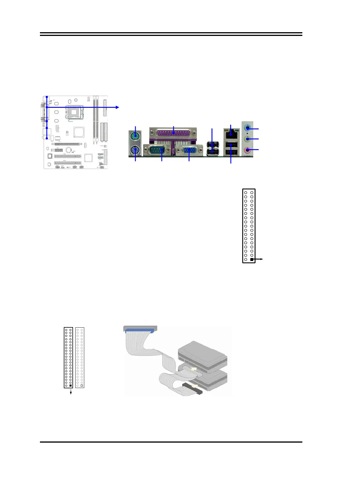
Audio Line-In,
Lin
-Out, MIC Connector :
This Connector are 3 phone Jack for LINE-OUT, LINE-IN, MIC
Line-in : (BLUE)
Audio input to sound chip
Line-out : (GREEN)
Audio output to speaker
MIC : (PINK)
Microphone Connector
(7) Floppy drive Connector (34-pin block): FDD1
This connector supports the provided floppy drive
ribbon cable. After connecting the single plug
end to motherboard, connect the two plugs at
other end to the floppy drives.
(8)Primary IDE Connector (40-pin block): IDE1
This connector supports the provided IDE hard disk ribbon cable. After connecting the
single plug end to motherboard, connect the two plugs at other end to your hard disk(s).
If you install two hard disks, you must configure the second drive to Slave mode by
setting its jumpers accordingly. Please refer to the documentation of your hard disk for
the jumper settings.
Primary IDE Connector
Pin 1
IDE1
Floppy Drive Connector
Pin 1
FDD
LINE-OUT
LINE-IN
MIC
COM1
VGA
USB
USB1
PS/2 Keyboard
PS/2 Mouse PRINT
Optional
LAN
 Loading...