VIA Technologies, Inc.
VT82C42
-8-
XTAL1
XTAL2
CLOCK (1-12 MHz)
Figure 6. Clocking from other clock source for VT82C42
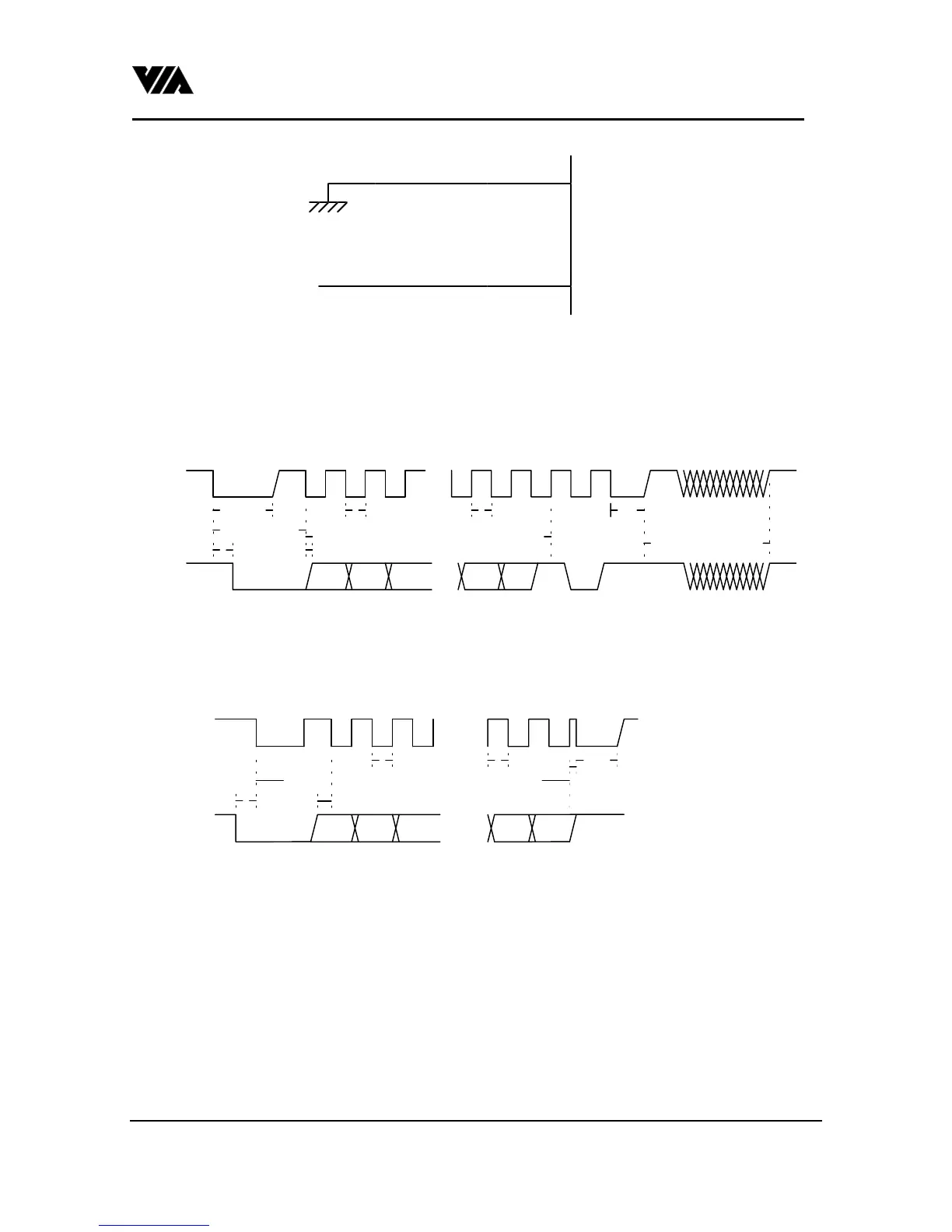
2. A transmission from Keyboard Controller to external device
* bitp means parity bit, bits means stop bit.
* CLOCK is driven by external device except the leading 250µs & ending 60µs low time.
* DATA is driven by KBC except the low time after the stop bit.
* If the maximum (a), (b), or (c) cannot be met, KBC will terminate the transmission with a timeout error.
DATA
CLOCK
bit0 bit1 bit2
250us
.......
.......
90us
bitp
60us
15ms max.(a) wait for response end
20ms max. (c)
2ms max. (b)
6us max.
30us min.
bit7 bits
Fig 7.Timing from KBC to external device
3. A transmission from external device to Keyboard Controller
* CLOCK is driven by external device except the ending 60µs low time.
* DATA is driven by external devices.
* If the maximum (a) cannot be met, KBC will terminate the transmission with a timeout error.
.......
CLOCK
DATA bit0 bit1 bit2
.......
bitp
3us min.
30us min.
3us min.
60us
8us2ms max. (a)
bit7
Fig 8.Timing from external device to KBC
4. Upon recieving commands which program the output ports from the host , the controller will put the
corresponding data to the output port within 6 clocks. There is one exception, P
20
is connected to system reset
on a typical desktop application. For software compatibility the output of P
20
is delayed for 4~8µs.