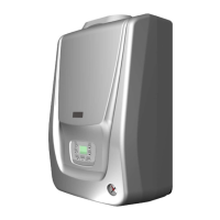
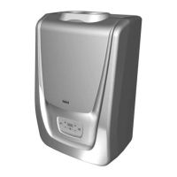
19
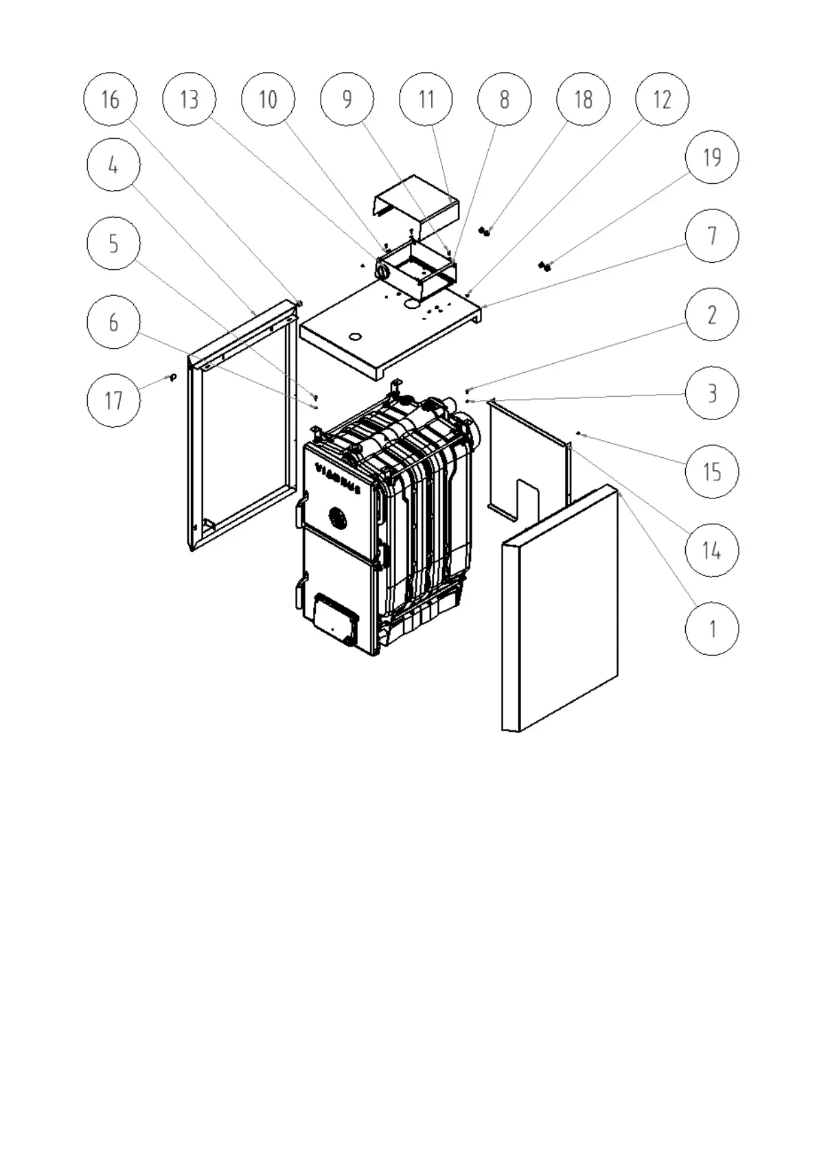
1. Right side part of the jacket
2. Screw M5 x 12
3. Washer 5,3
4. Left side part of the jacket
5. Screw M5 x 12
6. Washer 5,3
7. Upper part of the jacket
8. Košer part of the control box
9. Screw M5 x 12
10. Washer 5,3
11. Upper part of the control box
12. Screw M 5 x 12
13. Thermomanometer
14. Rear part of the jacket
15. Screw ST 4,2 x 9,5
16. Bushing HEYCO
17. Slant bushing
18. Blind flange 15,9 (3 ks)
19. Blind flange 19 (1 ks)
Fig. no. 18 Jacket assembly of the boiler with the box
Mounting of the draw barof smoke flap control
1. Complete the smoke flap control according to Fig.no.19.
2. Fasten the smoke flap control draw bar (2) to the smoke flap (1) by means of lock 2,5 x 20 (3).
3. Screw the plastic ball M10 (4) to the front part of the draw bar
4. Stick the label of smoke flap control.


 To Next Page