DIGITAL
DIGITAL
DIGITAL
DIGITAL
MULTIMETER
MULTIMETER
MULTIMETER
MULTIMETER
OPERATION
OPERATION
OPERATION
OPERATION
MANUAL
MANUAL
MANUAL
MANUAL
1.
1.
1.
1.
INTRODUCTION
INTRODUCTION
INTRODUCTION
INTRODUCTION
The instrument is a high performance, high accuracy , 3
3
/
4
digit , 42mm digit
high LCD multi-meter for measuring DC and AC voltage, DC and AC current,
Resistance and Capacitance, Frequency, temperature, duty circle, Transistor, Diode
and Continuity test. Design parameter: unit indication, data hold (HOLD), relatively
measuring (REL), AUTO/MANUAL range, auto off and buzzer sounds, etc.
The Dual-slop A/D converter CMOS technology for auto-zero, polarity
selection and over-range indication. Full overload protection is provided. Because
of its outstanding features, it is most suitable for use on production lines or for lab,
R & D, mainten ance and repair work.
2
2
2
2
.SPECIFICATIONS
.SPECIFICATIONS
.SPECIFICATIONS
.SPECIFICATIONS
2.1
2.1
2.1
2.1
GENERAL
GENERAL
GENERAL
GENERAL
SPECIFICATIONS
SPECIFICATIONS
SPECIFICATIONS
SPECIFICATIONS
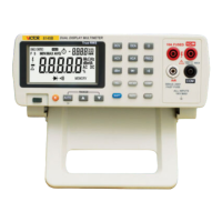
Display: 3 3/4digit LCD with a max readings of 3999
Measuring method: Dual - slop integrating A/D converter system.
Sampling rate: Approx. 3times/second.
Max. Common Mode Voltage: 500V DC/AC RMS.
Range select method: Automatic and Manual
Polarity: Automatic negative polarity indication.
Over range indication: Only the MSD “ OL ” display.
Low battery
:
The “ ” displays .
Safety standards
:
EMC/LVD. The meter is up to the standards of IEC1010
Pollution Degree 2, Over voltage category Ⅱ or double insulation Ⅱ .
Operating environment: Temperature (0 ~ 40) ℃ , humidity<80%RH.
Storage environment: Temperature (-10~50) ℃ , humidity<80%RH.
Power: Double, standard 1.5 volt battery. AAA 7# battery.
Dimension: 190mm (H) × 93.5 mm (W) × 3 7mm (D).
Weight: Approx. 4 20g(including battery).
2.2
2.2
2.2
2.2
ELECTRICAL
ELECTRICAL
ELECTRICAL
ELECTRICAL
SPECIFICATIONS
SPECIFICATIONS
SPECIFICATIONS
SPECIFICATIONS
Accuracy is ± (percentage of reading + number of digit) at(23 ± 5) ℃ ,<75%RH.
DC
DC
DC
DC
Voltage
Voltage
Voltage
Voltage
Input impedance: 400mV range: more th an 40M Ω other range: 10M Ω
Overload protection: 1000V DC or AC peak value
DC
DC
DC
DC
mV
mV
mV
mV
:
:
:
:
AC
AC
AC
AC
Voltage
Voltage
Voltage
Voltage
Input impedance: 400mV range: more th an 40M Ω ; other range: 10M Ω
Frequency response: 750V range
:
40-100Hz other range: 40-400Hz
Overload protection: 1000DC/750VAC RMS
Indication
:
mean value response (rms of sine wave)
Resistance
Resistance
Resistance
Resistance
Overload protection
:
250V DC/AC peak value
Open circuit voltage: 400mV
Note: at 400 Ω range, should short the test leads and measure the resistance of the wire,
then, minus from measuring.
DC
DC
DC
DC
Current
Current
Current
Current
Overload protection : 0.5A/250V fuse, 10A/250 V fuse.
Max measuring voltage: Full scale mA range: 1.2V ; A range
:
100
mV.
Max input current: 10A ( max. up to 15 seconds).
AC
AC
AC
AC
mV
mV
mV
mV
AC
AC
AC
AC
Current
Current
Current
Current
Overload protection : 0.5A/250V fuse, 10A/250 V fuse
Max measuring voltage: Full scale mA range: 1.2V A range: 100 mV
Max input current: 10A (up to 15 seconds).
Frequency response: 10A range: 40-100Hz; other range: 40-400Hz
Capacitance
Capacitance
Capacitance
Capacitance
Overload protection : 250V DC/AC peak value
Frequency
Frequency
Frequency
Frequency
Input sensitivity: 1.0V
Overload protection: 250V DC/AC peak value
Diode
Diode
Diode
Diode
and
and
and
and
continuity
continuity
continuity
continuity
Test
Test
Test
Test
Overload Protection
:
250V DC/AC peak value
Warning: do not input voltage at the range for safety.
Transistor
Transistor
Transistor
Transistor
hFE
hFE
hFE
hFE
Test
Test
Test
Test
Temperature
Temperature
Temperature
Temperature
Thermocouple: K type
Warning: do not input voltage at the range for safety.
3.
3.
3.
3.
FRONT
FRONT
FRONT
FRONT
PANEL
PANEL
PANEL
PANEL
DESCRIPTION
DESCRIPTION
DESCRIPTION
DESCRIPTION
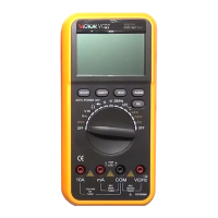
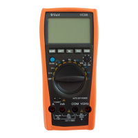
1.LCD
2. Function key
2-1.HOLD Key
2-2.REL Key
2-3.Hz/DUTY Key
2-4 “ select ” key
2-5.RANGE Key
3.Rotary Switch
4.V oltage, Resistance, Frequency socket.
5.COM input jack terminal
6.Less than 400mA input jack terminal
7.10A input jack terminal
4.OPERATION
4.OPERATION
4.OPERATION
4.OPERATION
1
.
Check the 1.5 -volt battery
by
setting the ROTARY Switch remove s to OFF position.
If the battery is weak, a sign will appear on the display. If this does not appear on
the display, proceed as below. See MAINTENANCE if the battery has to be replaced.
2
.
The mark, or sign next to the lead jacks, is for warning that the input voltage or
current should not exceed the indicated values.
This is to prevent from damaging the internal circuits.
3
.
The function switch should be set to the range that you want to test before operation.
4
4
4
4
.1
.1
.1
.1
DC
DC
DC
DC
Voltage
Voltage
Voltage
Voltage
measurement
measurement
measurement
measurement
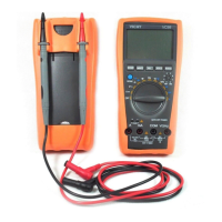
1) Insert the BLACK test lead to “ COM ” jack and RED test lead to the “ V/ Ω /Hz ”
jack.
2 ) Set the FUNCTION switch to “ ” range.
3) The d efault range is Auto range, and "AUTO" is displayed. Pressing RANGE key
switch to manual range, 400mV/4V/40V / 400V/1000V can be select ed
.
4) Connect the test leads to the tested point, the voltage and polarity which connected
with the red lead will appear on LCD.
Note:
Note:
Note:
Note:
1) Manual range, if LCD display "OL", over range is being indicated and the
FUNCTION switch must be set to a higher range.
2) Do not measure over 1000V , or, the meter will be damaged.
3) Caution to avoid contact with high voltage circuits when measuring high voltage.
Display read approx. forward
voltage of diode
Forward DC Current
approx.0.5mA. Reversed
voltage approx.
1.5V.
Buzzer sounds if resistance
Between terminals V/ Ω a nd COM
is less than about 7 0 ± 30 Ω .
Open circuit voltage:
0.5V
Base Current ap p rox.
15uA, Vce approx. 1.5V
<
<
<
<
400 ℃ ± ( 1.0 %+ 5 d)
≥ 400 ℃ ± (1.5%+15d)