Sensor:TP01(K type thermocouple)
CAUTION:DO NOT INPUT VOLTAGE AT THIS RANGE!
4. OPERATION
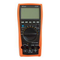
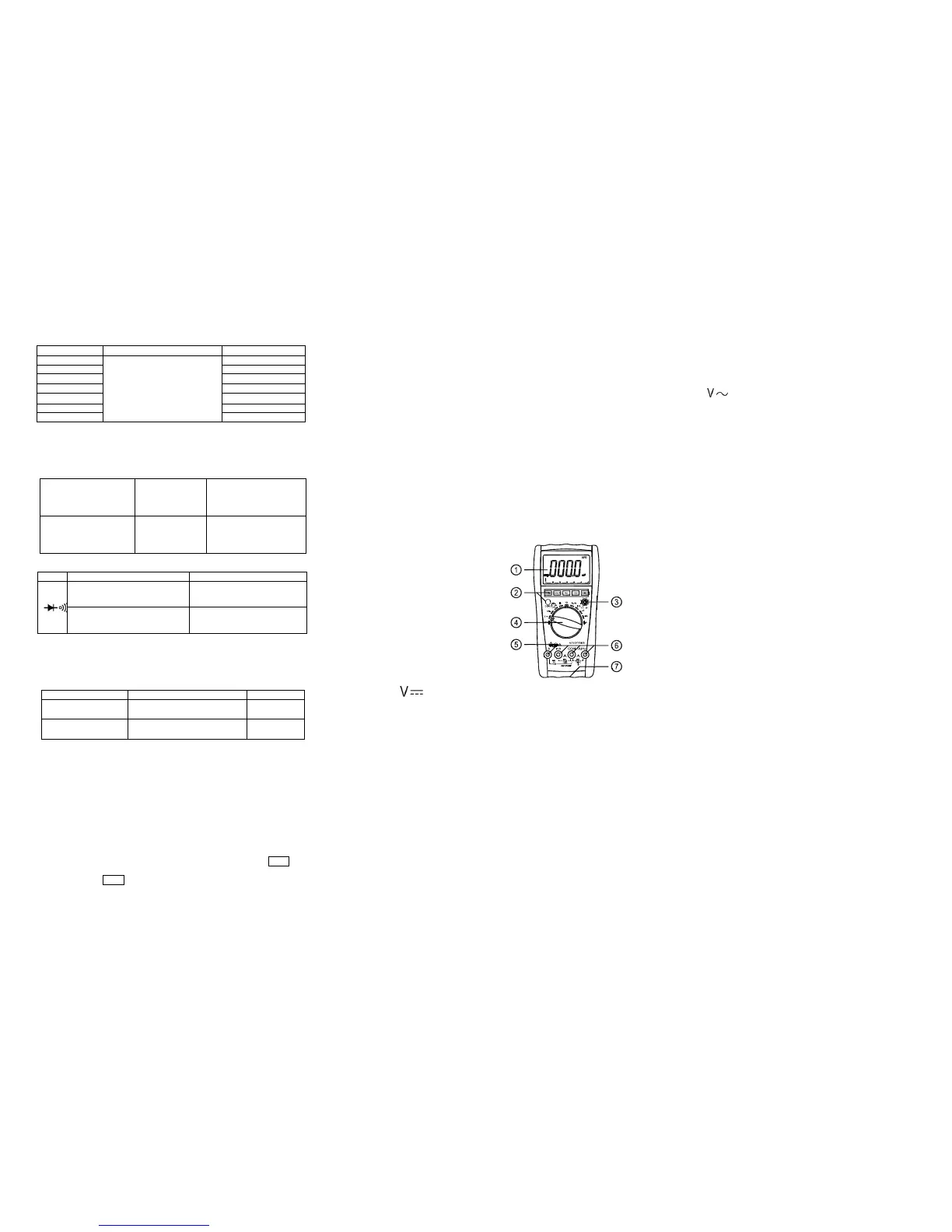
4-1. Panel description
1. LCD: display the measuring value and unit.
2.Function key:
2-1.HOLD key:press it, the presently measured value is held on LCD and HOLD symbol
displays. Press it again, HOLD symbol disappears, and the meter is exited the holding mode.
2-2. REL key:press it,reading clear,turn into relative value measurement states,“REL”symbol
displays, Press it again,“REL” symbol disappears, and the meter is exited the relative mode.
2-3. Hz/DUTY key:When measuring the AC Voltage (Current),press it,it will switch
Frequency/duty cycle/Voltage(Current) , When measuring the Frequency ,it will switch
frequency/duty cycle(1~99%)。
2-4.”DC/AC”key: switch DC and AC work mode..
2-5.RANGE key:select auto range or manual range mode, Auto range is the original states, it
will display ”AUTO” symbol ,press it change to manual range .Press it more than 2 second , it
will return to auto range states
2-6.MAX/MIN key :press it, turn into MAX mode, it will hold the max value of measuring,
press it again ,turn into MIN mode, it will hold the min value of measuring. No auto power off
and analog bar display under this mode. Press it more than 2 second , it will exit MAX/MIN
states.
3. hFE transistor COM
4. Knob:Switch measuring function and range.
5. Temperature COM
6. Voltage、Current、resistance、frequency and GND
COM.
7.battery case.
See picture 1
4-2.DCV measuring
1.Select the knob to range.
2. Insert the black test lead to “COM” terminal and the red one to “V/Ω/Hz” terminal.
3.Auto range is the original states, it will display ”AUTO” symbol,press “RANGE” key
change to manual range mode,600mV、6V、60V、600V、1000V range is selective;
4. Connect the leads crossly to the electric circuit under test; LCD displays polarity and voltage
under test connected by the red test lead.
Note:
1. Firstly users should select the knob to the highest range, if users had no idea about the range
of voltage under test, and then select the proper range based on displaying value. If LCD
displays “OL”, it means meter is over the max. Value of this range, thus should select the knob
to a higher range.
2. Do not input a voltage over DC 1000V.
3. Be carefully while measuring a high voltage. DO NOT touch the high voltage circuit.
4.When the measuring voltage large than DC1000V ,the built –in buzzer will be sounds.
4-3.ACV measuring
1.Select the knob to “ ” range;
2. Insert the black test lead to “COM” terminal and the red one to “V/Ω/Hz” terminal.
3. Auto range is the original states, it will display ”AUTO” symbol,press “RANGE”key
change to manual range mode,6V、60V、600V、750V range is selective;
4. Connect the leads crossly to the electric circuit under test, LCD displays voltage by the test
lead.
Note:
1. Firstly users should select the knob to the highest range, if users had no idea about the range
of voltage under test, and then select the proper range based on displaying value. If LCD
displays “OL”, it means meter is over the max. Value of this range, thus should select the knob
to a higher range.
2. Do not input a voltage over AC 750V.
3. Be carefully while measuring a high voltage. DO NOT touch the high voltage circuit.
4.When the measuring voltage large than AC750V ,the built –in buzzer will be sounds.
4-4.DCA measuring
1.Insert the black test lead to “COM” terminal and the red one to “mA” terminal (the Max.
600mA) or to “20A”(the Max.20A);
2.Select the knob to a proper DCA range, press “DC/AC” key to select the measurement mode,
then connect the leads crossly to the electric circuit under test; LCD displays polarity and
current under test connected by the red test lead.
Note:
1. Firstly users should select the knob to the highest range, if users had no idea about the
range of current under test, and then select the proper range based on displaying value .
2. If the LCD displays “OL”,it means the current is over range. Now you need to select the
knob to the higher.
3. Max. input current is 600mA or 20A(subject to where the red test lead insert to), too
large current will damage the fuse.
4-5.ACA measuring
 Loading...