EasyManua.ls Logo

VICI VC97A - User Manual

VICI VC97A
4 pages
Print Icon
To Next Page IconTo Next Page
Loading...
DIGTAL MULTIMETER
Operation Manual
1. General Description
This is a 3 3/4 digital multimeter with high stablility and performance. It uses a LCD with
20mm high figure, which makes the reading clearer and the operation more convenient. It
can test DCV, ACV, DCA, ACA, resistance, capacitance, frequency, NCV, duty cycle,
temperature, diode, and continuity. This meter also designed with functions including unit
symbol display, data hold, lighting, auto range, auto power off and warning functions. To
assure high accuracy and resolution, it adopts integrated circuit 8-bit microprocessor and a
dual integral A/D conversion as LCD driver, giving high resolution and high accuracy. It is
an ideal tool for labs, factories and radio-technology.
2. Safety Instructions
The instrument VC97A is designed in compliance with IEC1010 standard (safety standard
issued by International Electro technical Committee). Please read the following safety
instructions before operation.
2.1 Check the connection and insulation of test leads to avoid electric shock.
2.2 To avoid electric shock and damage to the meter, do not input voltage exceeding rated
value.
2.3 When measuring voltage higher than DC 60V or AC 40V, please be careful and avoid
electric shock.
2.4 Select correct function and range to avoid wrong operation.
2.5 Move the test leads away from test points when switching to other function.
2.6 Don’t input voltage in current terminal.
2.7 Don’t make any modification to the circuit. It may damage the meter or jeopardize
safety.
2.8 Safety symbols:
High voltage, “ GND, Dual insulation, “ ” Refer to manual, Low
battery indication.
3. Features
3.1 General Characteristics
3.1.1 Display: LCD;
3.1.2 Max display: 4000 (3 3/4 digits, automatic polarity, and unit symbol display);
3.1.3 Measurement method: Analog to digital converter (in micro processor ADC+MCU);
3.1.4 Sampling rate: approx.3 times/sec.
3.1.5 Over-range display: “OL” displayed.
3.1.6 Low battery indicator: “
3.1.7 Working environment: (040), relative humidity: <80%;
3.1.8 Store condition: (-1050), relative humidity: <80%
3.1.9 Battery: 2 pieces 1.5V battery (“AAA” 7# battery);
3.1.10 Dimension: 185×93×35mm (length x width x height);
3.1.11 Weight: approx. 290g (including battery);
3.1.12 Accessories: test leads, TP01 thermocouple, user manual, holster, gift box, and
2*1.5V batteries.
3.2 Technical Features
3.2.1 Accuracy: ± (a% × reading + digits). To assure accuracy, the ambient temperature
should be (23±5) , relative humidity <75%. One year accuracy is guaranteed since
production date.
3.2.2 DC VoltageDCV
Range Accuracy Resolution
400mV
±(0.5%+5d)
0.1mV
4V 1mV
40V 10mV
400V 100mV
1000V ±(1.0%+5d) 1V
Input impedance: at 400mV range >40MΩ, at other ranges is 10MΩ.
Overload protection: 1000VDC or 750VAC peak value.
3.2.3. AC VoltageACV(True RMS)
Range Accuracy Resolution
400mV ±(1.5%+10d) 0.1mV
4V
±(0.8%+10d)
1mV
40V 10mV
400V 100mV
750V ±(1.0%+10d) 1V
Input impedance: at 400mV range >40MΩ, at other ranges is 10MΩ.
Overload protection: 1000VDC or 750VAC peak value.
Frequency response: at 750V range: (40~1000)Hz, at other ranges: (40~2000)Hz
Displaying: True RMS response (calibration based on sine wave RMS)
3.2.4 DC CurrentDCA
Range Accuracy Resolution
400uA
±(1.0%+5)
0.1μA
4000uA 1μA
40mA 10μA
400mA 100μA
4A 1mA
20A ±(2.0%+5) 10mA
Maximum voltage drop: 400 mV for full mA range, 200 mV for full A range.
Maximum input current: 20A (within 10 seconds).
Overload protection: 0.5/250V fuse and 13A/250V fuse.
3.2.5 AC Current (ACA)
Range Accuracy Resolution
400uA
±(1.5%+10)
0.1μA
4000uA 1μA
40mA 10μA
400mA 100μA
4A 1mA
20A ±(2.0%+10) 10mA
Maximum voltage drop: 400 mV for full mA range, 200 mV for full A range.
Maximum input current: 20A (within 10 seconds).
Overload protection: 0.5/250V fuse and 13A/250V fuse.
Frequency response: at 20A range: (40~100)Hz, at other ranges: (40~400)Hz.
Question and Answer IconNeed help?

Do you have a question about the VICI VC97A and is the answer not in the manual?

VICI VC97A Specifications

General IconGeneral
Display TypeLCD
Measurement TypeDigital Multimeter
DC Voltage Range200mV/2V/20V/200V/1000V
Resistance Range200Ω/2kΩ/20kΩ/200kΩ/2MΩ/20MΩ
Diode TestYes
Continuity BuzzerYes
Data HoldYes
Temperature Range-20°C to 1000°C
DC Current Range200μA/2mA/20mA/200mA/10A
AC Current Range200mA/10A
Capacitance Range2nF/20nF/200nF/2μF/20μF
Frequency Range2kHz/20kHz
Battery Type9V
Weight380g

Summary

General Description

Safety Instructions

Safety symbols

Explains safety symbols: high voltage, GND, dual insulation, low battery indication.

Features

General Characteristics

Overview of meter's display, measurement method, sampling rate, and indicators.

Technical Features

Details accuracy, ambient temperature, and year accuracy guarantee.

DC Voltage (DCV)

Specifies DC voltage ranges, accuracy, resolution, input impedance, and overload protection.

AC Voltage (ACV) (True RMS)

Details AC voltage ranges, accuracy, resolution, input impedance, and frequency response.

DC Current (DCA)

Lists DCA ranges, accuracy, resolution, voltage drop, input current, and overload protection.

AC Current (ACA)

Provides ACA ranges, accuracy, resolution, voltage drop, input current, and frequency response.

Resistance (Ω)

Outlines resistance ranges, accuracy, resolution, open circuit voltage, and overload protection.

Capacitance (C)

Lists capacitance ranges, accuracy, resolution, and overload protection.

Frequency (F)

Specifies frequency ranges, accuracy, resolution, input sensitivity, and overload protection.

Transistor (hFE)

Explains hFE measurement, display range, and test conditions for transistor testing.

Diode and Continuity Test

Details diode forward voltage drop and continuity test conditions.

Temperature (°C)

Covers temperature ranges, accuracy, resolution, and conditions for K-type thermocouple.

Operation

Panel Description

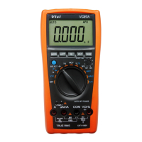
Identifies LCD display, control buttons, and input terminals.

DCV measurement

Step-by-step guide for measuring DC voltage using the multimeter.

ACV measurement

Instructions for performing AC voltage measurements with the multimeter.

DCA measurement

Detailed steps for measuring DC current with the multimeter.

ACA measurement

Guide on how to measure AC current using the multimeter.

Resistance measurement

Steps for measuring resistance, including auto/manual range and zeroing.

Capacitance measurement

Procedures for measuring capacitance, including discharge and REL key usage.

FREQUENCY MEASUREMENT

Instructions for measuring signal frequency using the multimeter.

NON-CONTACT VOLTAGE (NCV) DETECT

Explains how to use the NCV detection function and its limitations.

Transistor hFE measurement

Guide on measuring transistor hFE gain using the multimeter.

Diode and Continuity test

Steps for testing diodes and continuity using the multimeter.

TEMPERATURE MEASUREMENT

Instructions for measuring temperature using the thermocouple.

Data hold

How to use the data hold function to freeze readings on the LCD.

Auto power off

Explanation of the auto power off feature and how to disable it.

METER MAINTENANCE

Trouble Shooting

Related product manuals