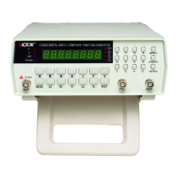
1. < ◄ > blinking bit shifts left 2.< ☼ > blink a c tivation key 3. < ► > blinking bit shifts right
4. < + > blinking number increase and positive level DC offset 5. < - > blinking number decrease and negative level DC offset 6. <F> frequency setting displaying
key 7 . <V> voltage setting displaying key 8. <MOD> functional mode selector 9. < ∆ f> spacing frequency key
10. < f
0
> 400Hz inter-modulation signal and sweeping initial frequency setting key 11. < f
1
> 1000Hz inter-modulation signal and sweeping terminal frequency setting key
12. < ∆ t> frequency sweep time interval setting key 13. <%> modulation depth setting key 14. <RST> reset key
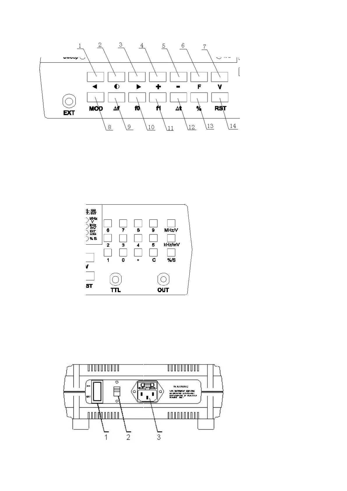
3-3. NUMBER KEY AREA : consists of 15 keys, see the fig.
Among them, there are 10 number keys: “ . ” Decimal point key
,
“ C ” backspace key , “ MHz/V ” MHz or V unit key
,
“ KHz/mV ” KHz or mV unit key
,
“ Hz/%/S ” Hz unit
key or modulation depth % or S unit key
3-4. TERMINAL DESCRIPTION :
TERMINAL 1 ( EXT ) outer-modulation signal input terminal ; TERMINAL 2 TTL level square wave output terminal ; TERMINAL 3 . sine wave output terminal
3-5. REAR PANEL DESCRIPTION : SEE THE FIG.
1. POWER SWITCH 2.220V/110V SWITCHER 3. POPWER SOCKET AND FUSE BOX ( 0.5A )
4.
4.
4.
4.
DIRECTIONS
DIRECTIONS
DIRECTIONS
DIRECTIONS
FOR
FOR
FOR
FOR
USE
USE
USE
USE
:
4-1.
4-1.
4-1.
4-1.
START-UP
START-UP
START-UP
START-UP
:
 Loading...