Firstly, check if the voltage and frequency of the power can match the instrument, and set the AC 220V/110V switcher to a correct position, then, plug in the power cord, turn on
the power
,
LED will display the
model
“ 2003
”
,
after 2 seconds, the instrument goes into operating mode.
We
suggest that before operation, the instrument should be preheated f or
3 0 minutes.
4-2.
4-2.
4-2.
4-2.
DATA
DATA
DATA
DATA
INPUT
INPUT
INPUT
INPUT
:
There are two ways for data input: 〈 1
〉
digital input: input by number keys from right shift to left shift, if exceed the resolution, input can not be done. If the data is out of scope, wi ll
output the proximal data. If wrong input, press “ C ” to clear the final bit, then ,input correct data. When finishing input, only when unit is input, will the data be input into the
instrument. During this procedure, the output signal is still output according to the previous data output. The way is suitabl e for the input of random value. 〈 2 〉 data modification: to
active the digit by “ ☼
”
key in the function area
,
press “ ◄
”
and “ ►
”
key can change the digit needed to be modified; press “ +
”
or “ -
”
key to increase or decrea se da ta.
To
cancel the mode, press “ ☼ ” key again. During this procedure, the output varies continuously. The way is suitable for modifying and input proximal data.
4-2-1.FREQUENCY
4-2-1.FREQUENCY
4-2-1.FREQUENCY
4-2-1.FREQUENCY
SETTING
SETTING
SETTING
SETTING
Press “ F ” key in the function area, the indicator will light, and the current output frequency value will be displayed on LED. If want to change frequency, input frequency value
directly, during input, the previous frequency will not be changed. If the input data is over 8-digit or over scope, the proximal frequency will be set. If wrong input, if do not input unit,
the data can be modified.
To
keep the original data, press “ F ” key.
When the input frequency value is close to the primary one, press “ ☼ ” key to active the final bit so long as the current displaying is frequency value, and it is unnecessary to
press “ F ”
key.
Press “ ◄ ” or “ ► ” key can select the digit needed to be modified, press “ + ” or “ - ” key can increase or decrease the value and can increase or decrease bit
continuously. The frequency of the output signal is in synchronism with that of displaying and will not be interrupted.
For example, if output a signal of 3.5KHz
,
take the following operation:
press “ F ” key , then, press “ 3 ” , “ . ” , “ 5 ” , “ KHz/mV ” in turn
If output a signal of 0.56MHz
,
take the following operation:
press “ F ”
key,
then, press “ 0 ” , “ . ” , “ 5 ” , “ 6 ” , “ MHz/V ” in turn; It
is
the same to press “ 5 ” , “ 6 ” , “ 0 ” , “ KHz/mV ” .
4-2-2.
4-2-2.
4-2-2.
4-2-2.
AMPLITUDE
AMPLITUDE
AMPLITUDE
AMPLITUDE
AND
AND
AND
AND
DC
DC
DC
DC
OFFSET
OFFSET
OFFSET
OFFSET
SETTING
SETTING
SETTING
SETTING
:
Press
“ V
”
key in the function area, and the indicator lights, the current output amplitude value will be displayed on LED, the value is the peak-peak value on high resistance load. If
t
he
load is 50 Ω , the actual output peak-peak value of the voltage is just a half of this value.
You
can input directly by number keys and vernier control by function keys, the concrete
operation is similar to frequency input.
For example, if want to output a signal with amplitude 10V
P-P
Press “ V ”
key,
then, press “ 1 ” , “ 0 ” , “ MHz/V ” key in turn.
If there is a certain DC video component in the output AC signal, i.e., need to DC offset or drift, press “ V
”
key in function area, then, “ +
”
or
“ -
”
key,
input the polarity of D CV
which needed to be offset, and the LCD will display “ P — ***
”
, it refers to the current DC drift rate (high resistance), thence, input the DCV value needed to be offset.
For example, if the output signal drifts +2.5V
Press “ V ” key and then “ + ”
key,
input “ 2 ” , “ . ” , “ 5 ” , “ MHz/V ” in turn.
Every time, when turn on the power or reset, the DC drift will be the default value
0V.
4-2-3.
4-2-3.
4-2-3.
4-2-3.
MODE
MODE
MODE
MODE
SETTING
SETTING
SETTING
SETTING
:
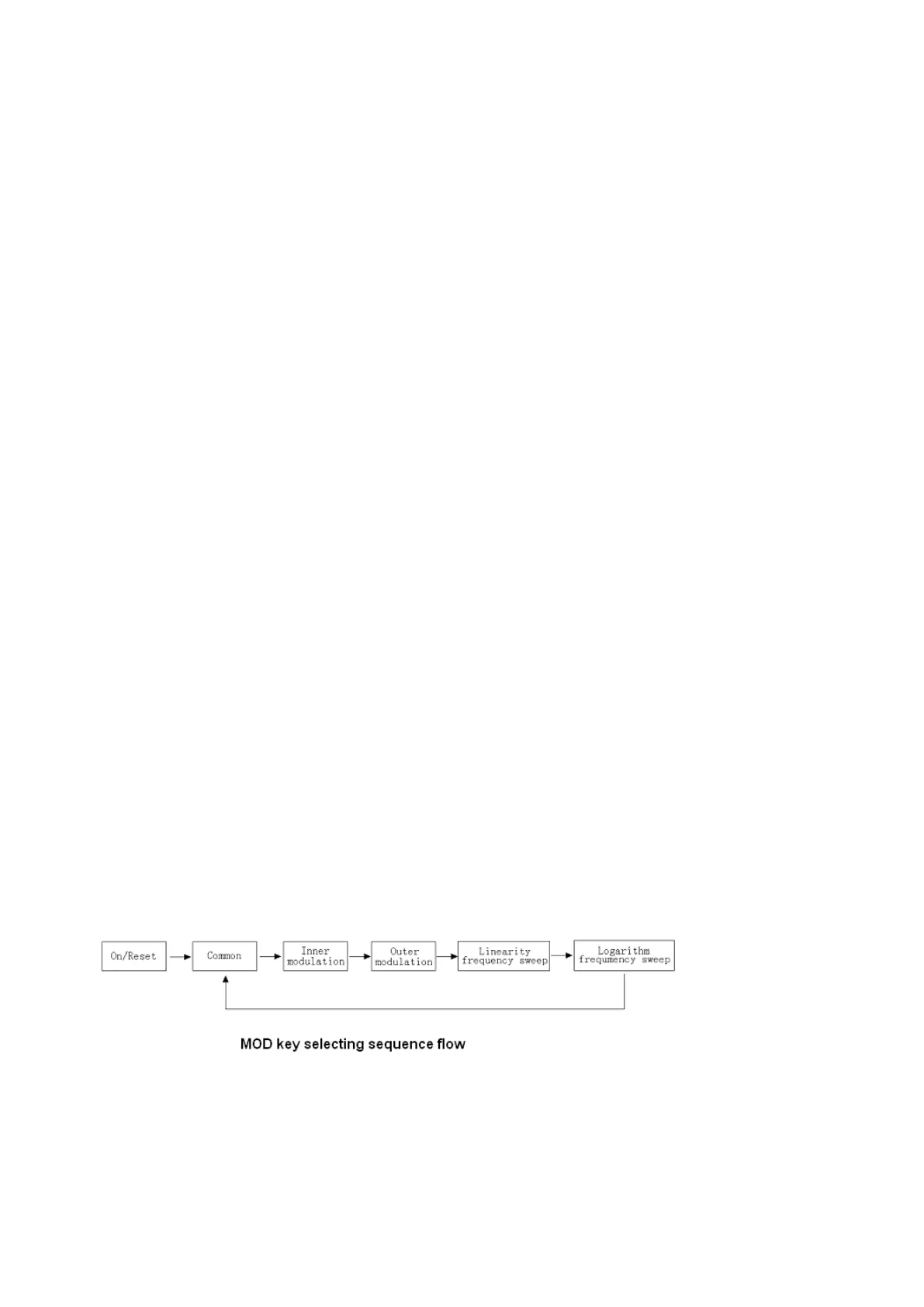
The “ MOD ” selector can select output mode, in turn, there is
:
COMMON
*
→ INNER- MODULATION → OUTER- M ODULATION → LINEARITY FREQUENCY SWEEP →
LOGARITHM FREQUENCY SWEEP → COMMON →… recycled , see the fig.
4-2-3-1.
4-2-3-1.
4-2-3-1.
4-2-3-1.
COMMON
COMMON
COMMON
COMMON
MODE
MODE
MODE
MODE
: it refers to the mode only set “ F ” and “ V ”
,
and it is the default mode for the instrument. 。
4-2-3-2.
4-2-3-2.
4-2-3-2.
4-2-3-2.
INNER
INNER
INNER
INNER
MODULATION
MODULATION
MODULATION
MODULATION
SETTING
SETTING
SETTING
SETTING
:
Press
“ MOD
”
selector to select inner-modulation mode, “ AM
”
indicator lights, the instrument is in inner-modulation mode.
Press
“ F
”
key to set carrier wave;
press
“ V
”
key to set the
amplitude of output signal; press “ %
”
key to set modulation
depth
( modulation factor
)
. There are 2 modulation signals for inner-modulation: 400Hz and 1000Hz
,
press f
0
to sel ect
400Hz modulation signal , the instrument displays “ 0 — 0.400kHz , press f
1
to select 1000Hz modulation signal, the instrument displays “ 0 — 1.000kHz .
For example, if want to get a signal with carrier frequency 630KHz , frequency of modulation signal is 1000Hz , modulation depth is 30% and output amplitude is 2V
P-P
:
Press “ MOD ” key to be into inner-modulation mode;
 Loading...