EasyManua.ls Logo

Victory FSA - User Manual

Victory FSA
28 pages
Print Icon
To Next Page IconTo Next Page
Loading...
INSTALLATION AND OPERATING INSTRUCTIONS
for all Hydrocarbon
FSA Freezer Models
3779 CHAMPION BLVD, WINSTON-SALEM, NC 27105
Phone: (888) 845-9800 | Fax: (800) 253-5168 | Web: victoryrefrigeration.com
809-191A Rev B. 10/29/2020
SEE BACK COVER FOR
WARRANTY REGISTRATION
Question and Answer IconNeed help?

Do you have a question about the Victory FSA and is the answer not in the manual?

Overview

This document is an installation and operating manual for Victory Hydrocarbon FSA Freezer Models, providing comprehensive information for safe operation, maintenance, and troubleshooting.

Function Description:

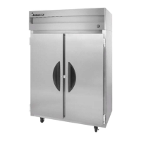
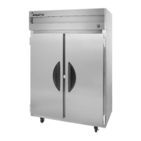
The Victory FSA Freezer is a commercial refrigeration unit designed to maintain product temperatures at -10°F. It is intended for use in commercial applications such as bars and restaurants. The unit operates by blowing warm air out from the top area and cool air from an inside blower. The refrigeration system operates at maximum when on, and the compressor and condenser fan motor activate when the internal cabinet temperature exceeds the set point. The unit features an electronic controller for temperature management and defrost cycles.

Important Technical Specifications:

  • Temperature Capability: Capable of maintaining product temperature at -10°F.
  • Electrical Requirements: All models are 115 volts, 60 Hz AC.
  • Plugs: Equipped with either a 5-15P or 5-20P plug, depending on the model.
  • Refrigerant: Uses R-290 hydrocarbon refrigerant. Charge numbers are provided per system for models with two refrigeration systems.
  • Construction: FSA models have aluminum liners, while FS models have stainless steel liners.
  • Dimensions: Cabinet dimensions (width x depth x height) vary by model and section count (1, 2, or 3 sections). Heights include casters.
    • 1-Section Models:
      • FS(A)-1D-S1-HC: 26 1/2 x 34 7/8 x 84 1/8 inches (Full Solid Door)
      • FS(A)-1D-S1-HD-HC: 26 1/2 x 34 7/8 x 84 1/8 inches (Half Solid Door)
      • FS(A)-1D-S1-HG-HC: 26 1/2 x 33 5/8 x 84 1/8 inches (Half Glass Door)
      • FS(A)-1D-S1-PT-G-HC: 26 1/2 x 38 3/4 x 84 1/8 inches (Full Glass Door)
      • FS(A)-1D-S1-PT-HC: 26 1/2 x 38 3/4 x 84 1/8 inches (Full Solid Door)
      • FS(A)-1D-S1-PT-HD-HC: 26 1/2 x 38 3/4 x 84 1/8 inches (Full Solid Door)
      • FS(A)-1D-S1-PT-HG-HC: 26 1/2 x 36 3/4 x 84 1/8 inches (Half Glass Door)
      • FS(A)-1N-S1-HC: 31 1/4 x 30 3/4 x 84 1/8 inches (Full Solid Door)
      • FS(A)-1N-S1-HD-HC: 31 1/4 x 30 3/4 x 84 1/8 inches (Half Solid Door)
    • 2-Section Models:
      • FS(A)-2D-S1-EW-PT-G-HC: 58 3/8 x 30 1/4 x 84 1/8 inches (Full Glass Door)
      • FS(A)-2D-S1-EW-HC: 58 3/8 x 34 7/8 x 84 1/8 inches (Full Solid Door)
      • FS(A)-2D-S1-EW-HD-HC: 58 3/8 x 34 7/8 x 84 1/8 inches (Half Solid Door)
      • FS(A)-2D-S1-EW-HG-HC: 58 3/8 x 33 1/2 x 84 1/8 inches (Half Glass Door)
      • FS(A)-2D-S1-EW-PT-G-HC: 58 3/8 x 35 7/8 x 84 1/8 inches (Full Glass Door)
      • FS(A)-2D-S1-EW-PT-HC: 58 3/8 x 38 5/8 x 84 1/8 inches (Full Solid Door)
      • FS(A)-2D-S1-EW-PT-HD-HC: 58 3/8 x 38 5/8 x 84 1/8 inches (Half Solid Door)
      • FS(A)-2D-S1-EW-PT-HG-HC: 58 3/8 x 36 1/8 x 84 1/8 inches (Half Glass Door)
      • FS(A)-2N-S1-HC: 31 1/4 x 30 3/4 x 84 1/8 inches (Full Solid Door)
    • 3-Section Models:
      • FS(A)-3D-S1-HC: 77 3/4 x 34 7/8 x 84 1/4 inches (Full Solid Door)
      • FS(A)-3D-S1-HD-HC: 73 3/4 x 34 7/8 x 84 1/4 inches (Half Solid Door)
      • FS(A)-3D-S1-G-HC: 77 3/4 x 33 1/2 x 84 1/4 inches (Full Glass Door)
      • FS(A)-3D-S1-HG-HC: 77 3/4 x 33 5/8 x 84 1/4 inches (Half Glass Door)
      • FS(A)-3D-S1-EW-HC: 85 1/8 x 34 7/8 x 84 1/8 inches (Full Solid Door)
      • FS(A)-3D-S1-EW-HD-HC: 85 1/2 x 34 7/8 x 84 1/8 inches (Half Solid Door)
      • FS(A)-3D-S1-EW-G-HC: 85 1/2 x 33 3/8 x 84 1/8 inches (Full Glass Door)
      • FS(A)-3D-S1-EW-HG-HC: 85 1/2 x 33 1/2 x 84 1/8 inches (Half Glass Door)
  • Room Air Temperature Range: Minimum 60°F, Maximum 100°F.
  • Voltage Range: Minimum 103.5V, Maximum 126.5V.
  • Load Amps: Varies by model, e.g., 9.1A for 1-section models, 10.5A or 13.9A for 2-section models, and 13.9A for 3-section models.
  • Clearances: 12 inches at the top, 0.0 inches at the rear, 0.0 inches at the left side, 0.0 inches at the right side.
  • Approvals: UL Classified, UL EPH.

Usage Features:

  • Electronic Controller: The unit features an electronic controller with a display for current internal temperature and icons indicating compressor status, defrost, fans, energy saving, alarm, and temperature readout (°F/°C).
  • Temperature Setting: The factory set temperature is 0°F, but it can be adjusted by the user. Adjusting the set temperature lower does not speed up cooling.
  • Manual Defrost: A manual defrost can be initiated by pressing and releasing the "melting" or defrost button.
  • Door and Fan Operation: The internal fan operates when the compressor is on and doors are closed. The compressor and condenser fan motor activate when the internal cabinet temperature rises above the set point.
  • Shelf Installation: Shelves are installed using clips that secure into pilasters. Proper installation ensures stability and prevents injury. Shelves should not be overloaded.
  • Real-Time Clock: The electronic controller allows setting the real-time clock (hour, minute, day).
  • Alarm Codes: The controller displays alarm codes for various issues such as probe failures (Pb1, Pb2, Pb3, Pb4, Pb5, LINK2, Virtual), high/low temperature alarms (AH1, AL1, AH2, AL2), external alarm (EA), door open alarm (OPd), end of defrost time-out (Ad2), preheating alarm (Prr), clock alarm (E10), high/low voltage alarms (HiP, LoP), and general/high/low pressure switch alarms (nPA, LPA, HPA, PA).

Maintenance Features:

  • Warranty Registration: Users are required to register their warranty information online or by mail within ten days of installation.
  • Cleaning Schedule:
    • Cabinet: Daily wipe down, weekly interior cleaning.
    • Condenser Coil: Monthly inspection and cleaning as required.
    • Gaskets: Daily inspection to ensure hinges are tight.
    • Routine Maintenance: Annually.
  • Daily Exterior Cleaning: Wash with a mild, chlorine-free detergent and a soft sponge, rinse with clean water, and dry with a soft cloth. Polish with a soft cloth, wiping with the grain, and wipe weekly with stainless steel cleaner.
  • Weekly Interior Cleaning: Remove food and shelves, disconnect power, clean loose food particles, scrub with warm detergent solution and soft brush, rinse, air dry, return shelves, restore power, and return food once safe temperature is reached.
  • Condenser Cleaning:
    1. Unplug the unit from the power supply.
    2. Pull out the bottom of the top panel to disengage locking clips.
    3. Raise the hinged panel.
    4. Remove the panel stand from its clip and secure it into the notch in the front right corner of the raised panel.
    5. Examine the condenser surface; if dusty, brush and vacuum the dust and lint. Avoid disturbing wires. For greasy coils, professional cleaning with coil cleaner is recommended.
    6. To close, replace the stand, lower the panel, and push firmly to engage locking clips.
    • Note: Air filters are not recommended as they restrict cooling air flow.
  • Stainless Steel Cleaning Methods: Detailed methods are provided for various types of stains and discolorations, including smears, fingerprints, stubborn spots, baked-on splatter, heat tint, burnt-on foods, grease, tenacious deposits, and hard water spots, specifying appropriate cleaning agents and application methods.
  • R290 Service Guidelines (for certified technicians only):
    • Wire nuts are not to be used for electrical part changes.
    • Switches are sealed; only exact replacements may be used.
    • Process tubes are for service access.
    • Refrigeration components to be replaced must be cut out with a tubing cutter, not un-brazed.
    • R290 venting must occur in a flame/spark-free area near an open window or door.
    • A sign indicating propane in the system must be attached during service.
    • A combustible gas leak detector must be used.
    • Evacuation: Critical for leak-free and dry system; requires a good vacuum pump and micron gauge.
    • Charging: System is critically charged; proper type and amount must be weighed in.
    • Overcharge Symptoms: Cools properly but with unusually cold suction line temperature and longer compressor run time.
    • Undercharge Symptoms: Long run time, poor cooling, and a hot compressor dome.

Victory FSA Specifications

General IconGeneral
BrandVictory
ModelFSA
CategoryFreezer
LanguageEnglish

Related product manuals