5
2. Cancel button ESC
Back to the previous menu or cancel operation in the
operation menu
Back to the real-time surveillance during the playback state
3. Play preview file button
I
Play previous video during the playback state
4.
Play next file button
5. Show play
6. Fast play
7. Playback/pause button
8. play/pause button
9.
Network connection
indicator light
I
II
II
Play next video during the playback state
Play in the multi-low or regular speed video during the
playback state
Play in the multi-fast or regular speed video during the
playback state
Playback the video or pause during the playback state
Play the video or pause during the playback state
Network connects normally if lighted
10.
Alarm indicator light Trigger alarm if lighted
11.
Power indicator light Trigger alarm if lighted
12.
Recording indiacator light Trigger alarm if lighted
LINK
Table 2.1 Front panel button operation function table
No. Button name Mark Function
1.
Direction button
>
<
Surveillance pictures, into the single channel or
multi-channel image surveillance.
Change the setting in the menu
Add or decrease number during the user edit state
Remove the cursor
< >
Remove the cursor when the main menu or sub menu is
popped up
Remove the cursor during the playback mode
Enter former or after channel surveillance during single
surveillance image
Enter
Main menu / function
Confirm
Enter main menu or next grade menu
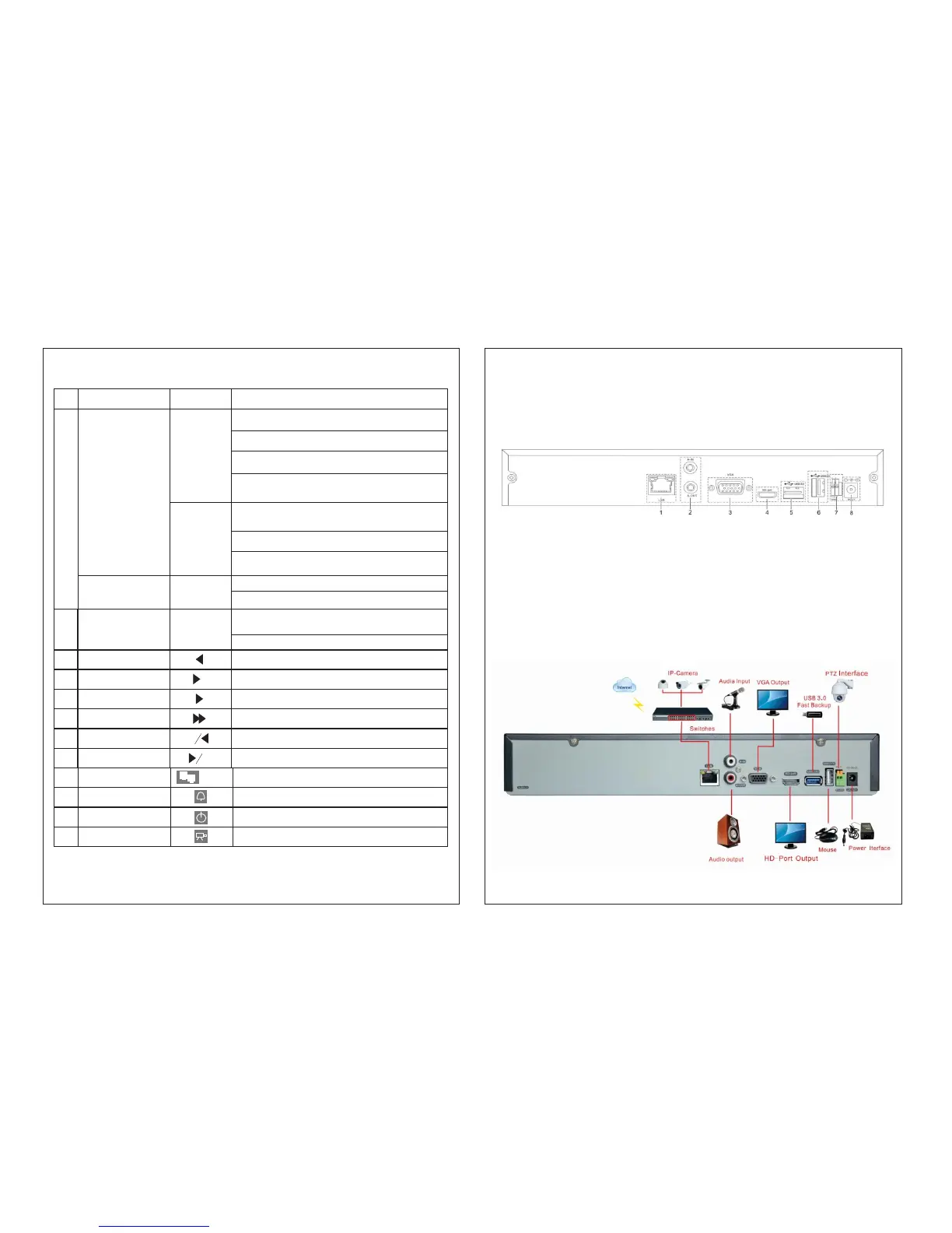
2.3 Understanding of the rear panel
Note: Below are rear panels of some of our representative models. Please take the real object as final, these
are Just for reference
(1) Network interface (2) Audio input/ audio output (3) VGA output (4) HDMI interface
(5) USB3.0 interface (6) USB2.0interface (7) RS-485 interface video (8)Power jack
Note: Some models have front panel USB interface, this interface with the top of the rear panel USB port are
mutually exclusive, only one interface is effective at the same time. USB at the bottom of rear panel is
independent and effective.
2.4 Installation connections sketch map
6