16
VIDEOMAN
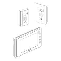
2 monitors and 1 doorstations
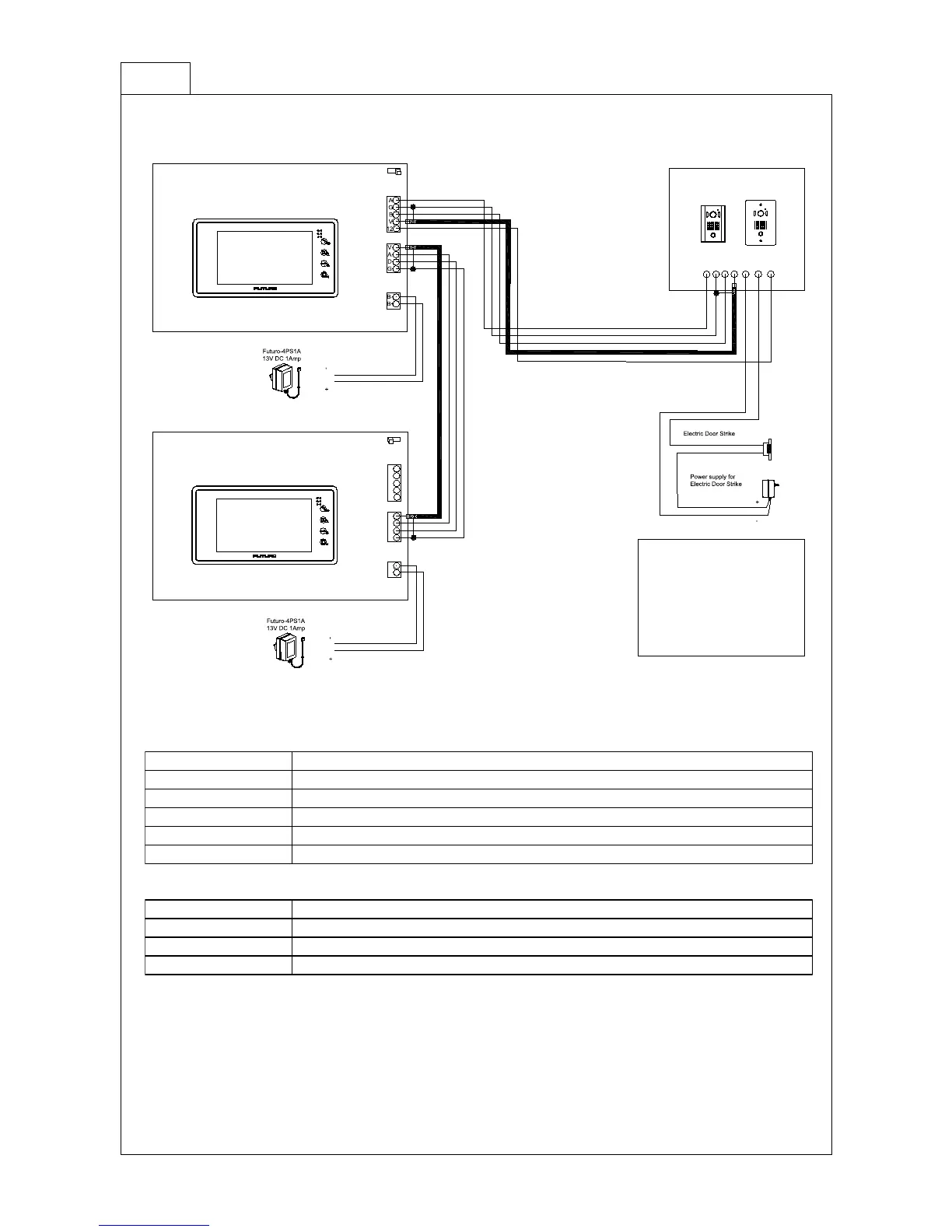
A G B V D/O D/O 12v
FUTURO-CZ4 or CP4
1
2
3
4
1
2
3
4
5
FUTURO-SD4
1
2
1
2
3
4
A
G
B
V
12
1
2
3
4
V
A
D
G
Camera
Sub-Monitor
Power
B-
B+
5
FUTURO-SD4
1
2
Camera
Sub-Monitor
Power
FUTURO-SD4M Connection Terminal
Description
5 Pin plug : CAMERA
1. AUDIO 2. GND 3. B+ 4. VIDEO 5. LED
4 Pin plug : SUB-MONITOR
1. VIDEO 2. AUDIO 3. DATA 4. GND
2 Pin plug : POWER
1. B- 2. B+
1 2
1 2
EOL
EOL
Note
1. Terminal description and voltage
Camera terminal
Audio appx 4.6VDC when Standby / 12V DC when Door Open
Constant power for the back light & Advanced recording 12V DC
Door open, Normal Open A contact
Video Normal: 0V DC, When Sub Monitor is on: appx 0.5V DC
Audio Normal: 4.6V DC, When intercommunicates: appx 3.6V DC
2. EOL ( End of Line ) signal termination switch setting : the first monitor "2" & the last monitor "1"
[ When more than 2 monitors are loop-in-loop-out (Daisy Chain) set the switch to "2" on
all monitors but the last one set to "1".
eg. Select "2" if another monitor is connected to the sub-monitor plug. ]
3. Maximum number of monitors in a system using loop-in-loop-out method is 3(three).
 Loading...