66251780 - V1.1 - 30/04/19
- 4 -
4000 Series
Art.4901 - Installation instructions
OPERATION
• Type in the programmed code and press ENTER;
• If the code is correct, the green LED will illuminate for approx. 2 seconds and the relay relevant to the code will operate for the
programmed time;
• If a wrong code is entered, a continuous melody will sound for 4 or more seconds, according to the number of mistakes;
• To switch o any relay while operating, type in the relevant code then press the CLEAR button;
OPERATION NOTES
• To operate relays together, set the same code for each relay;
• If a wrong code is entered, the system will lock out for 5 seconds which will increase each time a wrong code is entered. The system will
operate only when the correct code is entered.
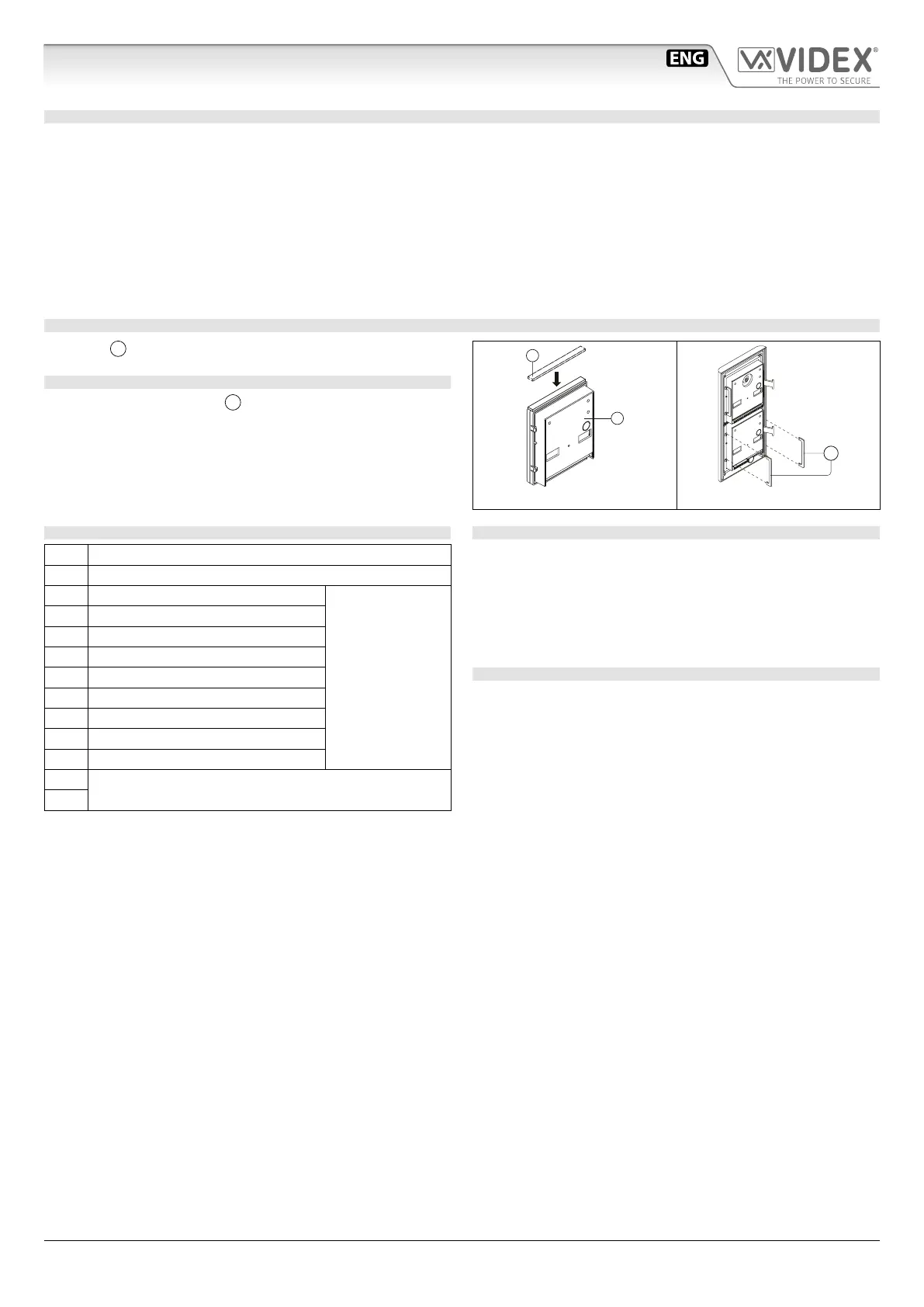
ADHESIVE GASKET PLACEMENT
Apply the
Y
seal as shown in Fig. 3.
ANTITAMPERING LOCKS FIXING
Fit the anti-tampering locks
W
as shown in Fig. 4.
Y
G
Fig. 3
W
Fig. 4
CONNECTION TERMINALS SIGNALS
SW2 Relay 2 command signal (active low)
SW1 Relay 1 command signal (active low)
NC3 Relay 3 normally closed contact
Max
24Vac/dc
3A
NO3 Relay 3 normally open contact
C3 Relay 3 common contact
NC2 Relay 2 normally closed contact
NO2 Relay 2 normally open contact
C2 Relay 2 common contact
NC1 Relay 1 normally closed contact
NO1 Relay 1 normally open contact
C1 Relay 1 common contact
12/24Vac/dc power input
+
CLEANING OF THE PLATE
Use a clean and soft cloth. Use moderate warm water or non-ag-
gressive cleansers.
Do not use:
• abrasive liquids;
• chlorine-based liquids;
• metal cleaning products.
TECHNICAL SPECIFICATION
Power Supply: 12/24 Vac/dc – 2VA
Power Consumption: Stand-by: 20mA
Operating: 70mA
Working Temperature: -10 +50° C
Art.4901 Digital codelock module
 Loading...