66251780 - V1.1 - 30/04/19
- 1 -
4000 Series
Art.4901 - Installation instructions
A B
C
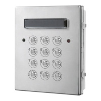
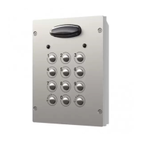
Fig. 1 Front
MOV
NO1 NC1
NO2 NC2
NO3 NC3
SW2
SW1
NC2
NO2
C2
NC3
NO3
C3
NC1
C1
–
+
NO1
Made in Italy
4901
STEEL
ALI
HIGH BRASS
MATTE
Note: Remove MOV
jumper completely
when using a relay to
trigger a gate controller.
A
B
JPL
ED
F
Fig. 2 Back
DESCRIPTION
The module features 12 buttons backlit keypad (Keys 0 - 9,
ENTER and CLEAR) and 2 LED’s for progress information dur-
ing use and programming. With three integral relays each with
common, normally open and normally closed connections and
two inputs to enable the external triggering of relays one and two (for example, push to exit button). Key presses are signalled both
acoustically and visually while each button press has a tactile feel. Entering the correct code followed by ENTER will activate the
relevant relay. Programming is carried out through the same keypad following a simple programming menu. The module can be
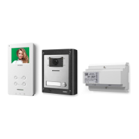
combined with other 4000 Series modules in an audio or video intercom system.
LEGEND
A
Green LED
B
Red LED
C
Backlit keypad
D
JPL jumper
E
MOV jumpers
F
Connection terminals
MAIN FEATURES
• 3 C, NC, NO relay outputs (24Vac/dc – 5A max);
• 3 Programmable secret codes (one for each relay);
• Each relay can be set to be activated for a specic time (01 to 99 seconds) or to work as latch;
• Two active low inputs to command directly the relay 1 and 2;
• Programming menu guarded by a 4-8 digit programmable engineer’s code;
• Visual and Acoustic signal during operating and programming;
• Keypad illumination LEDs;
GENERAL DIRECTIONS FOR INSTALLATION
In order to achieve the best results from the schematics described it is necessary to install only original VIDEX equipment, strictly
keeping to the items indicated on each schematic and follow these General Directions for Installation:
• The system must be installed according to national rules in force, in any case the running of cables of any intercom unit must be
carried out separately from the mains;
• All multipair cables should be compliant to CW1308 specication (0.5mm twisted pair telephone cable).
• Cables for speech line and service should have a max resistance of 10 Ohm
• Lock release wires should be doubled up (Lock release wires and power supply wires should have a max resistance of 3 Ohm);
• The cable sizes above can be used for distances up to 50m. On distances above 50m the cable sizes should be increased to keep
the overall resistance of the cable below the RESISTANCES indicated above;
• Double check the connections before power up;
• Power up the system then check all functions.
Art.4901 Digital codelock module
Rev.0.1