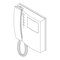
Two Wire Videokit ESVK Series
PrtCode:ESVK_ENG_1.3 – Pag.6/24
23/10/2008 Rev.1.3
Art.3181
Digital intercom for VX2300 2 Wire System
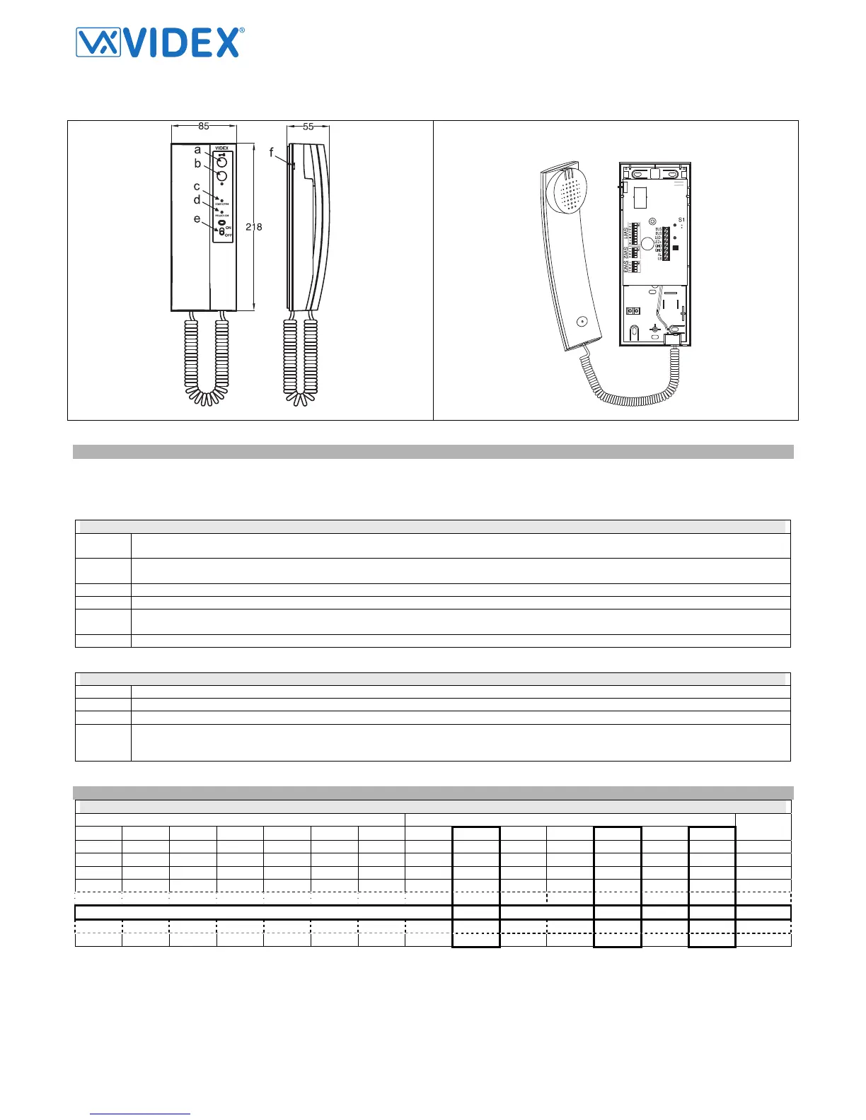
Fig.1 Fig.2
DESCRIPTION
Intelligent intercom with “door open/intercommunicating call” push button (key), bus relay (Art.2305) activation button (dot), “privacy ON-OFF” switch,
“door open” and “privacy on” LEDs and call tone volume control (3 levels). To avoid a BUS arrest in case a user forgot the handset picked up, each op-
eration must be executed within 10 seconds after the handset is picked up otherwise to perform an operation it is necessary to hang up the handset and
pick up it again.
PUSH BUTTONS, LEDS AND CONTROLS (FIG.1)
a Door open push button – Intercommunicating call. For an intercommunicating call, pick up the handset and press as many times as the
extension or address value to call (see SW3 Intercommunication Settings).
b Activate bus relay board Art.2305 push button. To activate a bus relay pick up the handset and press as many times as the address
value of the relay.
c Door Open LED. Switched ON if the door is open. Its correct operation depend from correct connection
d Privacy ON LED. Switched ON when the privacy service is active
e Privacy ON-OFF switch. The privacy duration time can be programmed. If the intercom is programmed for a specific privacy duration,
after the service is enabled switching to “ON” position (red LED ON), the service will be automatically
f Call tone volume control (3 levels)
DIP-SWITCHES AND JUMPERS (FIG.2)
SW1 Switches from 1 to 7 are used for unit address (from 1 to 127 binary coded). Last switch (8) is not used
SW2 Switches 2,3 and 4 are used to set privacy duration time. The switch 1 is not used.
SW3 Switches 1,2 and 3 are used to for intercommunication settings. The switch 4 is not used.
S1 Impedance terminator. The jumper must be normally closed. When more videophones/intercoms are connected in parallel (from a pe-
ripheral to another and so on until the last) the jumper must be open for all the intercoms except for the last following the connection or-
der.
PROGRAMMING
SW1 – INTERCOM ADDRESS
Switches Status Binary Code – Decimal Value
7 6 5 4 3 2 1 64 32 16 8 4 2 1
Decimal
Code
OFF OFF OFF OFF OFF OFF ON 0 0 0 0 0 0 1 1
OFF OFF OFF OFF OFF ON OFF 0 0 0 0 0 1 0 2
OFF OFF OFF OFF OFF ON ON 0 0 0 0 0 1 1 3
OFF OFF OFF OFF ON OFF OFF 0 0 0 0 1 0 0 4
OFF ON OFF OFF ON OFF ON 0 1 0 0 1 0 1 37
ON ON OFF OFF OFF ON ON 1 1 0 0 0 1 1 99
The table above shows how to set the address of the videophone. Considering that ON = 1 and OFF = 0, multiply each digit for the relevant decimal
weight then sum values obtained to get the address: E.g. as highlighted in the table OFF,ON,OFF,OFF,ON, OFF,ON in binary is equal to 0100101 then
multiplying each digit for the relevant decimal weight you obtain the address that is 37.
Note
The maximum number of units allowed is 64 but the address of each unit can be a value between 1 and 99
 Loading...