5
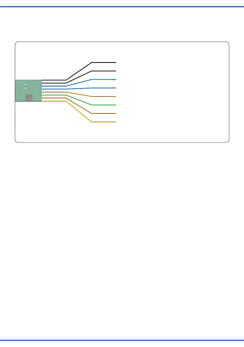
braun
gelb
brown
yellow
grün
green
orange
orange
blau
blue
blau
blue
schwarz
black
black
schwarz: durchtrennen für schnellere Schrankenbewegung
Black: cut this wire for faster barrier movement
blau mit grüner Markierung: Schranke schließen
Blue with green mark: lowering barriers
blau mit roter Markierung: Schranke öffnen
Blue with red mark: raising barriers
orange: Kontakt für Soundmodul und Blinkelektronik
Orange: connection for sound module and blinking module
grün: gemeinsamer Mittelpunkt für Soundmodul und Blinkelektronik
Green: common wire for sound module and blinking module
braun: Stromversorgung
Brown: power supply
gelb: Stromversorgung
Yellow: power supply
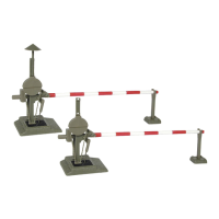
Fig. 3
Abb. 3
Blau mit roter Markierung:
Schranken werden geöffnet.
Blau mit grüner Markierung:
Schranken werden geschlossen.
Blue with red sleeve:
Barriers will be raised.
Blue with green sleeve:
Barriers will be lowered
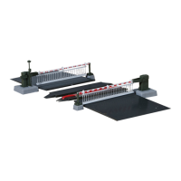
4. Montage
1. Zeichnen Sie die Positionen der Bohrungen für die
Schranken (1) und (2) mit Hilfe des in Abb. 4 abge-
bildeten Bohrschemas an. Die Mittelpunkte der Boh-
rungen müssen einen Abstand von 73 mm haben.
2. Bohren Sie an den angezeichneten Stellen jeweils
ein Loch mit einem Durchmesser von 13 mm für die
Schrankenantriebe.
3. Stecken Sie die Schranken mit dem Antrieb von oben
durch die Bohrungen.
4. Schieben Sie die Befestigungsringe von unten so auf
die Antriebe auf, dass die Rastnasen um 90° zu der
Riffelung am Gehäuse der Antriebe verdreht sind
(Abb. 2) und in der Riffelung des Antriebsgehäuses für
einen festen Halt sorgen. Hierbei sollten Sie die
Sockel der Bahnschranke von oben festhalten.
5. Bei Montage von Art.-Nr. 5104 stecken Sie die Wider-
lager in die entsprechenden Bohrungen ein. Bei Art.-
Nr. 5107 ist die Montage der Widerlager nicht not-
wendig.
6. Kleben Sie das Gleisfüllstück (8) bzw. (9) auf die
Schwellen zwischen den Schienenprolen im Be-
reich des Bahnüberganges. Bei Zweileitergleisen
(Roco, Fleischmann, Trix, Peco, Lima, usw.) verwen-
den Sie bitte das Gleiszwischenstück ohne Metall-
streifen und Anschlusskabel.
Für Mittelleitergleise (Märklin C, M und K, Trix
Express) verwenden Sie bitte das Gleiszwischenstück
mit Metallstreifen und rotem Anschlusskabel. Das rote
Anschlusskabel führen Sie zwischen den Schwel-
len nach unten (eventuell zuvor ein Loch bohren) und
schließen es am Mittelleiter-Fahrstromanschluss (rot
bei Märklin) an.
Zum Erstellen breiterer oder mehrgleisiger Übergänge
für H0 gibt es unter der Art.-Nr. 5105 (Zweileiter) und Art.-
Nr. 5106 (Mittelleiter) einen Ergänzungssatz mit jeweils
einem entsprechenden Gleiszwischenstück. Die Rampen
4. Mounting
1. Mark the positions for drilling the holes for the driv-
ing mechanism (1) and (2) with the aid of the drawing
showning.4.Thecentresoftheseholesmustbe73
mm apart from each other.
2. Drill a 13 mm hole each at the marked positions
through which the drive mechanisms will be inserted.
3. Insert the driving mechanisms from above into the
holes.
4.Pushthexingringsontothedrivingmechanisms
from below until their snap tabs sit at an angle of 90°
against the ribbing on the housing of the mechanism
(g.2)andarermlyarrested.Duringthisprocessyou
should hold down the base of the barrier form above.
5. When mounting item-No. 5104 insert the barrier sup-
ports into the appropriate holes. For part-No. 5104 to-
gether with 5107 the mounting of the barrier supports
is not necessary.
6.Gluetheinll(8)or(9)ontothesleepersbetweenthe
rails matching the location of the ramps. Please use
theinllwithoutthemetalstripandwirefortwo-rail
systems (Roco, Fleischmann, Trix, Peco, Lima, etc.).
Correspondingly use the one with the metal strip and
the red wire for tracks with centre pick-up (Märklin C,
MandKtracks,TrixExpress).Installtheredwireby
guiding it through a hole between the sleepers (you
may have to drill a hole for this purpose) and connect
it to the centre conductor of the track (red in case of
Märklin).
For realising wider level crossings or over several tracks
youmaypurchaseadditionalinlls,part-No:5105(two-
rail system) and part-No: 5106 (three-rail-system). The
ramps (6) serve to raise the road to the level of the
tracks.
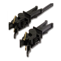
One drive mechanism is already connected to the con-
trol circuit board. The other one has to be connected by
means of the micro plug after installing the barrier.
 Loading...