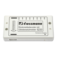
The arrow printed on the feedback decoder
must point in the direction of the digital con-
trol center!
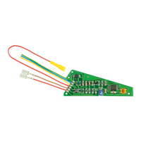
Please note that parts of the decoder are
very sensitive to static electricity!
Plug the special cable carefully onto the con-
tact pin (the pins bend easily)!
Special information for the memory:
Up to six 5233s can be connected to a Memory
from Märklin. The first decoder in the chain is for
activating the routes of key group “A”, and the sec-
ond for deactivating these routes. The third 4233 is
for activating the routes of key group “B”, etc. .
Special information for the Intellibox and the
Twin-Center:
The connection is made at the socket marked
“s88”. In the basic settings menu, you must en-
ter how many feedback decoders are connected
under the point “s88 settings”. Note that for each
two connected feedback decoders 5233, the value
must be increased by 1!
Example:
Six feedback decoders 5233 and one feedback de-
coder 5217 are connected.
The value (6 / 2 + 1) = 4 must be entered.
4. Connecting the Decoder to
the Track
Connecting to (Märklin) third-rail track:
Connect the propulsion power (“B”, red = “rt” and
“0”, brown = “br”) from the digital command station
or the booster to the “Fahrstrom-Eingang” socket
of the feedback decoder 5233.
Now insulate the third-rail at the beginning or the
end of the individual track sections that you want to
monitor (with the third-rail insulators of your track
system manufacturer). Then connect each of the
outputs 1 to 8 of decoder 5233 to one of these
electrically isolated third-rails.
Each power-consuming vehicle (with its own third-
rail pickup) which is located in one of these moni-
tored sections now generates a feedback message
to your digital command station (see Figure 2).
Connecting to two-rail / two-conductor sys-
tems:
Connect the propulsion power (“B”, red = “rt” and
“0”, brown = “br”) from the digital command station
or the booster to the “Fahrstrom-Eingang” socket
of the feedback decoder 5233.
Insulate the track on one side at the beginning and
the end of the individual track sections that you
want to monitor (e.g. with insulating track connec-
tors). Then connect each of the outputs 1 to 8 of
the decoder 5233 to one of these electrically iso-
lated rail profiles.
Each power-consuming vehicle (with its own wheel
pickup or with axle insulation bridged with resistor
paint) that is located in one of these monitored sec-
tions now generates a feedback message to your
digital command station (see Figure 3).
Unmonitored track areas:
These areas should be powered via a small ad-
ditional connection (shown at page 11, Figure 5).
This prevents bridging of the track insulation be-
tween monitored and unmonitored sections due to
vehicles travelling over the insulations from caus-
ing interruptions in the occupied message. The
additional circuit guarantees, that the voltage drop
of the digital voltage, caused by the current sen-
sors in the 5233, in the monitored track areas is
the same as in the track areas which are not mo-
nitored. This is to avoid a reduction of the speed of
a locomotive entering the monitored area. This ad-
ditional module can be obtained from Viessmann
under item no. 5234.
Current-free stopping sections:
To be able to monitor stopping section switched to
current-free, the associated switch contact must be
bridged with a resistor of 1.5 kΩ (Viessmann item
number 6836, 10 pieces) as shown in figure 4 at
page 11. This is necessary so that a small moni-
toring current can flow. In the figure this is shown
using a two-rail, two-conductor system, but applies
similarly for Märklin rails.
Technical Specifications
Dimensions: 109 x 54 x 23.5 mm
3
Data format: s88-Format
Track power input:
Maximum input voltage 24 V = / ~
Outputs 1 – 8:
Maximum load on each output 3 A
Maximum load (sum) 4 A
Current sensitivity 1 mA
 Loading...