6
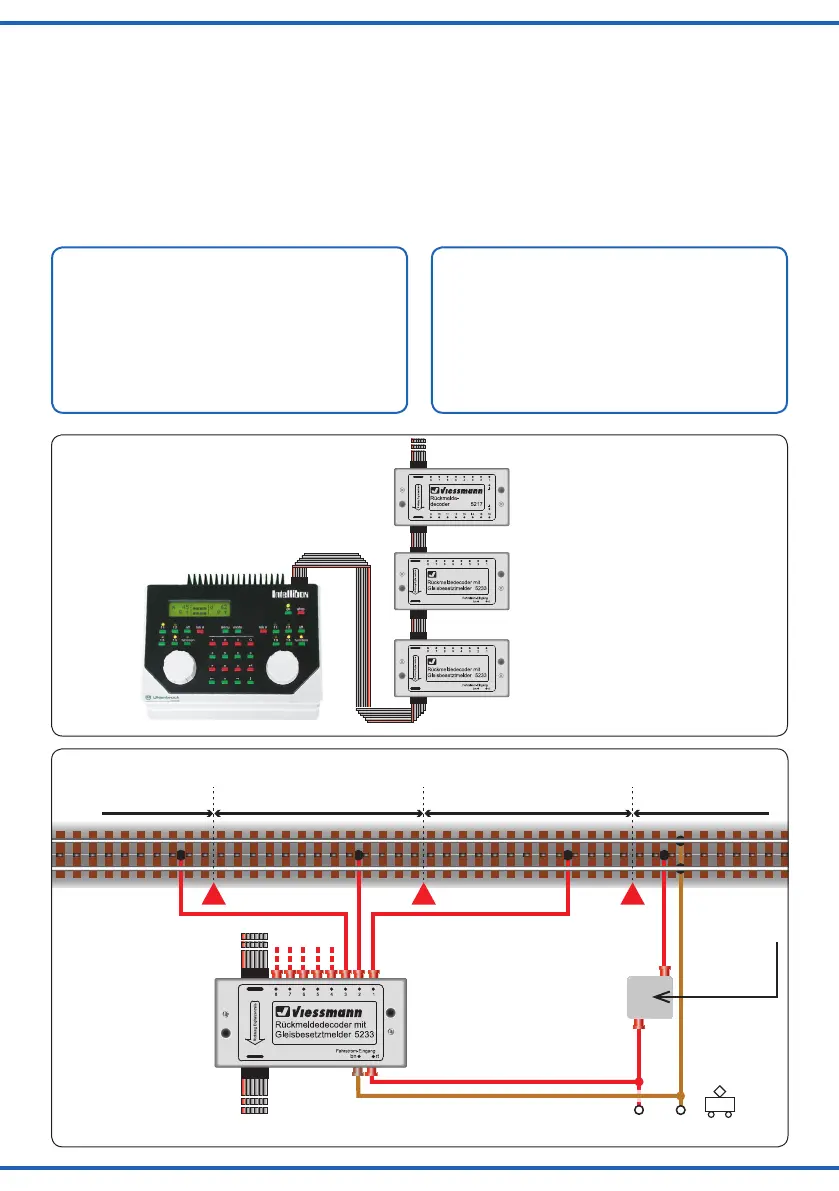
Abb. 1
Fig. 1
Abschnitt 1
Section 1
nicht überwacht
not monitored
Abschnitt 2
Section 2
Abschnitt 3
Section 3
5233
von weiteren Decodern
from further decoders
zur Digital-Zentrale
to the digital command station
Fahrstrom
traction current
braun („0“)
brown (“0”)
rot („B“)
red (“B”)
siehe Abb. 5
see g. 5
Viessmann
5234
Abb. 2
Fig. 2
4.4 Stromlose Halteabschnitte
Um stromlos geschaltete Halteabschnitte überwachen zu
können, muss der zugehörige Schaltkontakt mit einem
Widerstand von 1,5 kΩ (Art. 6836, VE 10 Stück) überbrückt
werden (siehe Abb. 4 auf Seite 11). Das ist notwendig,
damit ein kleiner Überwachungsstrom fließen kann. Dar-
gestellt ist der Anschluss für ein Zweischienen-Zweileiter-
sytem. Sinngemäß gilt dies auch für den Anschluss von
Märklin-Schienen.
5. Technische Daten
Datenformat: s88-Format
Fahrstrom-Eingang: 14 – 24 V Digital
Maximale Eingangsspannung 24 V DC= / AC~
Ausgänge 1 – 8:
Maximale Belastbarkeit pro Ausgang 3 A
Maximale Belastbarkeit (Summe) 4 A
Stromempfindlichkeit 1 mA
Maße: L 10,9 x B 5,4 x H 2,35 cm
4.4 Current-free stopping sections
To be able to monitor stopping sections switched to cur-
rent-free, the associated switch contact must be bridged
with a resistor of 1.5 kΩ (Viessmann item 6836, 10 pieces)
as shown in fig. 4 at page 11. This is necessary so that
a small monitoring current can flow. In the figure this is
shown using a two-rail, two-conductor system, but applies
similarly for Märklin rails.
5. Technical data
Data format: s88-Format
Track power input: 14 – 24 V digital
Maximum input voltage 24 V DC= / AC~
Outputs 1 – 8:
Maximum load on each output 3 A
Maximum load (sum) 4 A
Current sensitivity 1 mA
Dimensions: L 10.9 x W 5.4 x H 2.35 cm
Digital-Zentrale
Digital command station
(Eingänge 17 bis 32)
(inputs 17 to 32)
(Eingänge 9 bis 16)
(inputs 9 to 16)
(Eingänge 1 bis 8)
(inputs 1 to 8)
2
1b
1a
5217
5233
5233