Sekundär
0-10-16 V~
16 V
Primär
230 V~
Gefertigt nach
VDE 0570
EN 61558
Lichttransformator
5200
Nur für trockene Räume
Primär 230 V 50 - 60 Hz
Sekundär max. 3,25 A52 VA
ta 25°CIP 40
10 V
0 V
Universal Tasten - Stellpult
5547
Viessmann
grün
gelb
braun
rot
/ yellow
/ green
brown
/ red
4554
5547
5200
Fig. 13
Abb. 13
5. Anschluss und Einrichtung
Alle Anschluss- und Montagearbeiten dürfen nur
bei abgeschalteter Betriebsspannung durchge-
führt werden!
Verwenden Sie nur nach VDE /EN-gefertigte Mo-
dellbahntransformatoren!
Sichern Sie die Stromquellen unbedingt so ab,
dass es bei einem Kurzschluss nicht zum Kabel-
brand kommen kann!
Werkseinstellungen
Ab Werk ist der Decoder auf die Digitaladresse 1
(Motorola-Protokoll) eingestellt.
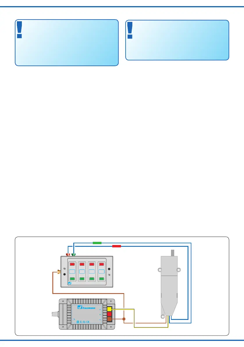
Konventioneller (analoger) Betrieb
Im konventionellen (analogen) Betrieb schalten Sie den
Weichenantrieb mit geeigneten Tastenstellpulten (z. B.
Viessmann Tastenstellpult 5547).
Schließen Sie den Weichenantrieb und das Tastenstell-
pult wie in Abbildung 13 gezeigt an. Verwenden Sie einen
geeigneten Transformator (z B. Viessmann 5200).
Digitalbetrieb
Im digitalen Betrieb schalten Sie den Weichenantrieb
über eine Digitalzentrale. Legen Sie als erstes eine Di-
gitaldresse fest. Lesen Sie dazu die beiden folgenden
Kapitel und beachten Sie Abb. 15.
Nach Festlegung der Digitaladresse schließen Sie den
Weichenantrieb an, wie in Abb. 14 gezeigt.
Wenn aufgrund der Eigenschaften Ihrer Weiche die Be-
wegungsrichtung nicht mit der Schaltrichtung auf Ihrem
Eingabegerät übereinstimmt, können Sie die Stellrich-
tung des Antriebs umkehren. Schließen Sie nach der Pro-
grammierung beide blaue Drähte gemeinsam an (s. Abb.
14.1): bei Märklin/Motorola beide Drähte an den Mittellei-
ter; bei DCC an eine beliebige der beiden Schienen.
Einrichtung mit DCC-Zentralen
Zur digitalen Steuerung des Weichenantriebs müssen Sie
diesem zunächst eine Digitaladresse zuweisen.
Zur Steuerung im DCC-System gehen Sie wie folgt vor:
5. Connection & Conguration
Make sure that the power supply is switched
off when you mount the device and connect the
wires!
Only use VDE/EN tested special model train
transformers for the power supply!
The power sources must be protected to prevent
the risk of burning wires.
Default settings
The factory setting for the digital address is 1 (Motorola
format).
Conventional mode of operation
(analogue)
In case that you use the Viessmann switch motor on con-
ventional layouts, use a push button panel (e. g. Viess-
mann Push Button Panel 5547).
Connect the switch motor and the push button panel
as shown in gure 13. Use a suitable transformer (e. g.
Viessmann 5200).
Digital mode of operation
In the digital mode of operation, you use a digital com-
mand station to control the switch motor. Please read
the following two chapters to learn how to set a digital
address.
Connect the switch motor to your digital layout as shown
in gure 14.
If the properties of your switch cause its motion to be the
opposite of the switching direction specied by your input
device, you have the possibility to reverse its direction.
After programming, connect both blue wires together
(gure 14.1): in a Märklin/Motorola system, connect both
wires to the middle rail; for DCC, connect both wires to
any of the two rails.
Congure with DCC central units
To use the switch motor in a digital environment, you
have to assign a digital address at rst. To control the
switch motor with a DCC-system, observe the following
instructions:
 Loading...