Fig. 5
Abb. 5
5.1 5.2
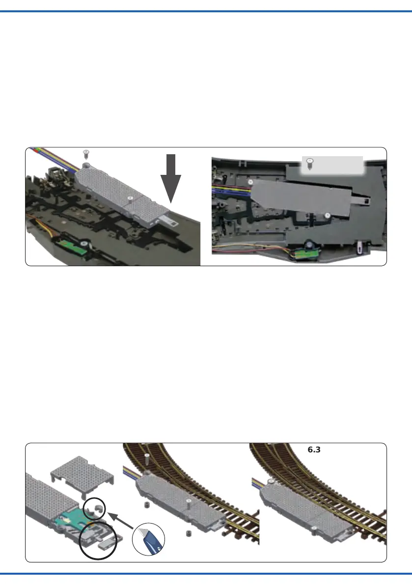
Fig. 6
Abb. 6
6.1 6.2 6.3
2,2 x 6 mm
Märklin C-Gleis (DKW)
Hebel: 1
Montage: in Bettung
1. Montieren Sie den Hebel gemäß Abbildung 3.1 (links)
im Weichenantrieb und verschließen Sie anschlie-
ßend das Gehäuse wieder.
2. Bringen Sie die Doppelkreuzungsweiche in die zum
Antrieb passende Stellung (Der Hebel des Weichen-
antriebs muss in den Hebel der DKW greifen).
3. Legen Sie den Weichenantrieb gemäß Abbildung 5 in
dieBettungderWeicheundxierenSieihnmitden
passenden Schrauben 2 x Nr. 13.
Roco-Line (ohne Bettung)
Hebel: 8 und 9
Montage: oberur,nebenGleis
1. Montieren Sie die Hebel gemäß Abbildung 6.1 im Wei-
chenantrieb und verschließen Sie anschließend das
Gehäuse wieder.
2. Entfernen Sie den markierten Befestigungsring an der
Einkerbung mit einem scharfen Messer.
3. Bringen Sie die Weiche in die zum Antrieb passende
Stellung (Der Hebel des Weichenantriebs muss in den
Hebel der Weiche greifen).
4. Montieren Sie den Antrieb neben der Weiche (Abb.
6.2)undxierenSieihnmitdenpassenden
Distanzhülsen und Schrauben 2 x Nr. 13.
Bei Verwendung der EKW und der DKW entfernen Sie
bitte den Steg im Hebel 9 (Abb. 9.1) und montieren Sie
den Antrieb mit dem Deckel nach unten.
Märklin C-track (Double Slip Switch)
Lever: 1
Mounting: Into bed of ballast
1. Mount lever 1 as shown in gure 3.1 into the switch
motor. After mounting the lever, close the casing with
the cover.
2. Bring the Switch into the corresponding position of the
switch motor (the lever of the switch motor has to get
connected with the lever of the switch).
3. Put the switch motor into the intended empty space of
the turnout as shown in gure 5.
Fix the switch motor with the screws 2 x nr. 13.
Roco-Line (without ballast)
Lever: 8 and 9
Mounting: Overground, beside the track
1. Mount lever 1 as shown in gure 6.1 into the switch
motor. After mounting the lever, close the casing with
the cover.
2. Cut off the fastening ring at the notch with a sharp
knife as shown in gure 6.1.
3. Bring the turnout into the corresponding position of the
switch motor (the lever of the switch motor has to get
connected with the lever of the turnout).
4. Mount the switch motor beside the turnout as shown
in gure 6.2. Fix the switch motor with the screws 2 x
nr. 13. Use the distance rolls!
When using a slip switch, cut off the bridge in lever 9 (see
gure 9.1) and mount the switch motor with the cover to
the ground.