Do you have a question about the Viessmann FT 0700 and is the answer not in the manual?
Units for coldrooms at -1°C to -25°C.
Units for coldrooms at -5°C to +19°C.
Warranty period, scope, and exclusions for functional faults.
Compliance with EMC Directive 2004/108/EC and Machinery Directive 2006/42/EG.
Indoor installation, ventilation, and ambient temperature for optimal operation.
Unit must be transported in intended position due to oil in the compressor.
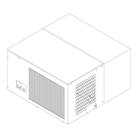
Unit supplied in three parts: evaporation unit, insulation housing, machine part.
Visual checks for damage, handling on lower part, keeping packaging for claims.
Tips for efficiency include avoiding heat sources and monitoring temperature.
Safe disposal of defective units and refrigerant according to regulations.
Instructions for connecting a remote control unit to the refrigeration unit.
Details on connecting multiple units via a bus line for remote control operation.
How to connect a door contact switch to switch off the fan when the door is open.
Connecting a potential-free fault indicator to the system for error reporting.
Safety precautions and procedures for connecting the unit to power and initial operation.
Describes normal display, button functions, and switching the unit on/off or initiating defrost.
Procedure for accessing and changing operational parameters using passwords.
Setting the evaporator fan operation for high or low relative humidity.
Changing the display language to German, English, or French.
Activating/deactivating a control lock to prevent unauthorized parameter changes.
Details on accessing parameters P02-P23 with passwords and parameter lists.
Lists fault codes (F01-F11) and their meanings for diagnosing issues.
Instructions for deactivating the unit for non-use or maintenance via plug or StandBy mode.
Comprehensive list of parameters (P28-P51) with descriptions, units, ranges, and default values.
Explains operational types and parameters, focusing on defrosting modes (x0, x1, x2, x3, 1y).
Details the condenser fan's operation, speed control, and fault handling.
How to set parameters P46-P49 for liquefaction temperature and fan speed control.
Using P50 and P51 to select unit type and reset parameters to factory defaults.
Observing DCF signal for time synchronization via parameter P28.
Adjusting temperature sensor readings using parameters P86 to P88 for accuracy.
Diagram illustrating the refrigerant flow path within the unit.
Electrical diagram for specific CT and FT unit models.
Electrical diagram for specific CT 3000 and FT 1500 unit models.
Refers to section 7.3 for a list of fault codes and their meanings.
How to activate emergency mode for continued operation during faults or regulator issues.
Provides a table of common faults, their causes, and suggested repair actions.