10
4.6 Einrichtung mit Motorola-Zentralen
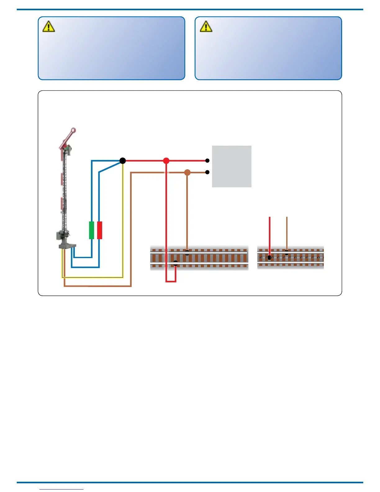
Damit Sie das Signal digital ansteuern können,
müssen Sie diesem zunächst eine Digitaladresse
zuweisen. Zur Steuerung im Märklin-Motorola-
System gehen Sie wie folgt vor:
1. Schalten Sie das Digitalsystem aus, z. B. Not-Aus.
Es darf keine Spannung mehr am Gleis anliegen.
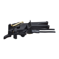
2. Verbinden Sie nur die grün markierte Steuer-
leitung und die Stromversorgungsleitungen des
Signals (braun und gelb, s. Abb. 6) mit dem Gleis.
– also nur 3 Kabel!
3. Schalten Sie das Digitalsystem ein.
4. Verbinden Sie die zweite, bisher oene (rot
markierte) Steuerleitung gleichfalls mit dem
Gleis (s. Abb. 6).
5. Senden Sie mit der Digitalzentrale nun für die
gewünschte Motorola-Adresse einen Schalt-
befehl. Das Signal empfängt den Befehl,
registriert die Adresse und quittiert dies durch
Umschalten.
4.6 Conguration with Motorola central units
To use the signal in a digital environment, you
have to assign a digital address at rst. To control
the signal with a Motorola-system, observe the
following instructions:
1. Switch o the digital system (e. g. emergency
o). There must not be any power at the rails.
2. Connect only the blue wire with the green
marking and the power supply wires of the sig-
nal (brown and yellow, g. 6) to the rails – so
only 3 cables!
3. Switch on the digital system.
4. Connect the up to now open second blue
wire (red markerd) to the track signal, too
(g. 6).
5. Use the digital command station to send a turn-
out-request for the desired Motorola-address.
The signal receives the request, registers the
address as its own and as a receipt, it switches
the signal.
Hinweis:
Sollte aufgrund der Eigenschaften Ihrer DCC/
MM Zentrale die Stellrichtung invertiert sein,
können Sie dies gemäß Abb. 7.1 korrigieren
oder durch Programmierung der CV 36 auf den
Wert 1 ändern.
Note:
If the switching direction is inverted caused by
the properties of your DCC/MM command
station you can correct this according to g.
7.1 or change by programming the CV 36 on
value 1.
DCC
Signale mit zwei ungekoppelten Flügeln: Das blaue Kabel mit
gelber Markierung wird im Digitalbetrieb nicht benötigt.
Signals with two uncoupled semaphore arms: the blue
wire with yellow marker is not required in digital mode.
Digital-
zentrale
Digital
Command
Station
Fig. 7.1Abb. 7.1
 Loading...