9
5. Senden Sie mit der Digitalzentrale nun für die
gewünschte DCC-Adresse einen Schaltbefehl.
Der Signalantrieb empfängt den Befehl, regis-
triert die Adresse und quittiert dies durch
Umschalten.
Damit ist das Signal unter der neuen Adresse
betriebsbereit. Falls Sie die Adresse künftig
ändern möchten, wiederholen Sie die Prozedur
einfach.
4.5 Programmieren am Programmiergleis
direkt an dem Programmierausgang von Zentra-
len, die DCC-kompatibel sind, vornehmen. Ver-
binden Sie dazu die Anschlüsse des Signals wie
in Abb. 6 gezeigt mit dem Programmierausgang
Ihrer Zentrale.
Die Adresse des Signals wird in 2 CVs program-
miert. In CV 1 steht das untere Byte (LSB) der
Adresse, in CV 9 das obere Byte (MSB).
Bitte beachten Sie, dass Signale mit zwei unge-
koppelten Flügeln zwei Adressen belegen.
Für die direkte Programmierung der Decoder-
adresse über CVs benutzen Sie bitte nachfol-
gende Tabelle. Sie können die benötigten CVs,
nämlich CV 1 und CV 9, berechnen, wenn Sie die
Decoderadresse durch 256 teilen. Das Ergebnis
kommt in CV 9, der Rest in CV 1. Die folgende
Tabelle enthält Beispiele.
Beispiele:
5. Use the digital command station to send a
turnout-request for the desired DCC-address.
The decoder receives the request, registers the
address as its own and as a receipt, it switches
the signal.
The signal is now ready to be used with the new
digital address. Whenever you want to change the
address, you just have to repeat the described
procedure.
4.5 Programming on the programming track
The conguration of the signal can also be
accomplished by connecting it directly to the pro-
gramming output of the command station. Sim-
ply connect the terminals of the decoder to the
programming output of the command station as
shown in g. 6.
The address of the drive is programmed in 2
CVs. In CV 1 you set the lower byte (LSB) of the
address, in CV 9 the upper byte (MSB).
Please note that signals with two uncoupled
semaphore arms require two addresses.
The address is established as described below.
Write the address value directly into CV 1 if you
want to assign an address between 1 and 255.
Set CV 9 to 0. Higher addresses than 255 must be
split into the MSB and the LSB: Divide the desired
address by 256 and determine the result without
decimal points as well as the remainder.
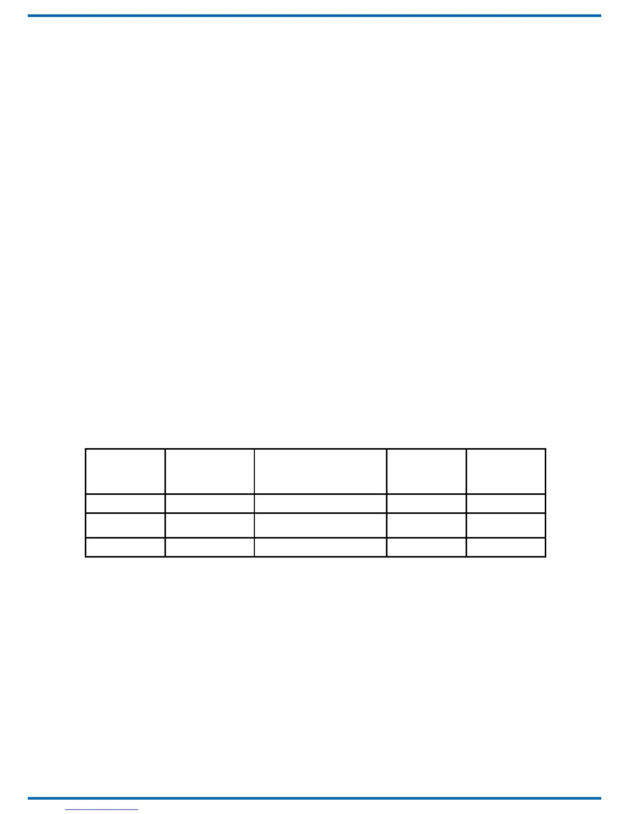
Examples:
Adresse/
Address
Ganzzahliges
Ergebnis/
Integer result
Rest CV 9 = MSB CV 1 = LSB
256 1 0 1 0
911 3 3 143
1025 4 4 1
Die weiteren Einstellmöglichkeiten entnehmen Sie
der CV-Tabelle. In CV 40 können Sie auch das Proto-
koll festlegen, auf welches das Signal später „hört“.
Auf Befehle am Programmierausgang einer
DCC-kompatiblen Zentrale reagiert der Decoder
immer unabhängig vom eingestellten Protokoll.
Bitte beachten Sie, dass einige Zentralen durch
den geringen Stromverbrauch das Signal am Pro-
grammierausgang nicht zuverlässig erkennen
können. Zur Abhilfe lesen Sie Kapitel 9.5.
Further programming options are listed in the CV-
table. You may also set the desired digital protocol
in CV 40.
The decoder will respond to commands of the pro-
gramming output of a DCC compatible command
station regardless of the set protocol.
Please note that due to the low current draw some
command stations may not be able to read out
data on their programming output. Read chapter
9.5 for potential remedies.
 Loading...