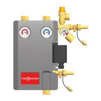
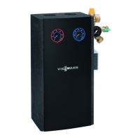
The Viessmann Solar-Divicon DN20B is a pre-assembled solar station designed for recirculating solar fluid in closed-loop solar thermal systems. It functions as a pumping station within the solar circuit, ensuring efficient heat transfer from the collector field to the storage tank. The station is mounted on a wall support and secured by clip springs, containing essential valves, fittings, and safety equipment for system operation.
Function Description:
The Solar-Divicon DN20B integrates several key components to manage the solar circuit:
- Solar Pump: A Wilo Star S16 U15-130 pump circulates the solar fluid.
- Ball Valves with Temperature Gauges: Located in both the supply (red spindle) and return (blue spindle) lines, these allow for isolation of sections and provide temperature readings. They are equipped with replaceable spindles and integrated immersion sleeves for the temperature gauges.
- Pressure Relief Valve: Set at 87 psi (6 bar), this safety device protects the system from overpressure.
- Pressure Gauge: Displays the system pressure, ranging from 0-87 psi (0-6 bar).
- Flowmeter: Allows for precise control and monitoring of the solar fluid flow rate, with a range of 0.8-6 USgpm (3-22 lpm). It includes a ball valve for isolation.
- Fill and Drain Valves: Connections (1.4 and 3.2) are integrated for flushing, filling, and draining the solar circuit.
- Airstop with Manual Bleeder: This component, located in the supply line, collects air liberated from the solar fluid, which can then be discharged via a vent plug. This ensures optimal ventilation of the solar circuit.
- Check Valves: Two integrated check valves (2 x 7.9 inch head or 2 x 200 mm wc) prevent unwanted gravity circulation within the system. These can be opened to facilitate air purging during initial commissioning.
- Connection for Expansion Tank: Allows for the connection of an external expansion tank to accommodate thermal expansion of the solar fluid.
The station's primary function is to control the temperature in the hot water storage tank by circulating solar fluid from the collector field. It ensures safety against pressure increases, enables exact flow rate control, facilitates flushing and draining, measures supply and return temperatures, deaerates the solar loop, and prevents gravity circulation. All functional and safety devices are housed within a thermal insulation case.
Important Technical Specifications:
- Dimensions:
- Total height: 15.9" (405 mm)
- Total width: 13.5" (344 mm)
- Depth: 5.9" (150 mm)
- Center distance supply/return: 3.9" (100 mm)
- Pipe Connections: 3/4" copper cutting-ring compression fitting. Can be reduced to 1/2" copper if required.
- Connection for Expansion Tank: 3/4" female thread, NPT.
- Outlet of Pressure Relief Valve: 3/4" female thread.
- Max. Admissible Pressure: 87 psi (6 bar).
- Max. Operating Temperature: 248°F (120°C).
- Short-term Load: 320°F (160°C) for < 15 minutes.
- Max. Propylene Glycol Content: 50%.
- Materials:
- Valves and fittings: Brass
- Gaskets: EPDM
- Check valves: Brass
- Insulation: EPP, λ = 0.043 W/(m K)
- Power Supply: 120 V / 60 Hz for the solar pump.
- Flow Rate for Optimal Ventilation: At least 0.3 m/s in the supply (0.63 USgpm for 1/2" pipe, 1.49 USgpm for 3/4" pipe).
Usage Features:
- Installation: Designed for indoor installation in a dry, stable, and frost-free environment. It comes fully pre-assembled on a steel wall support for quick and easy mounting using snap-lock technology.
- Commissioning: Involves flushing and filling the solar circuit, preparing for flushing by disconnecting the expansion tank and opening check valves to 45°, connecting a flush and fill station, and venting the system through the airstop. The solar loop flow rate is set via a 3-speed switch on the solar pump or, in exceptional cases, by adjusting the ball valve in the flowmeter.
- Safety: Incorporates a pressure relief valve and check valves to prevent gravity circulation. Safety instructions emphasize the importance of keeping ball valves with temperature gauges and the flowmeter open during operation to avoid disconnecting the safety assembly.
- Solar Fluid: Only Viessmann-specified solar fluid (water and propylene glycol mixture, max. 50% glycol) should be used. Flushing with water is discouraged due to frost damage risk.
- Electrical Connection: Requires a 120V 60Hz power supply from the solar controller to the solar station pump. Wiring can be routed through slots in the back foam insulation panel.
Maintenance Features:
- Cleaning: The exterior can be cleaned with a damp cloth; abrasive cleaners should be avoided. The shell must remain closed during cleaning.
- Partial Draining: Allows for replacement of components below the ball valves (e.g., the pump) without draining the entire collector array. This involves disconnecting the controller, closing the ball valves to 90°, connecting a heat-resistant hose to the drain valve, opening the drain valve, and carefully opening the airstop vent plug.
- Complete Draining: Necessary for replacing solar fluid, dismounting the station, or replacing seals above the ball valves. This follows partial draining steps, then opening check valves to 45°, and potentially opening bleeding devices at the highest point of the solar thermal system.
- Pump Replacement: Involves partial draining, disconnecting the pipe joint to the storage supply, dismounting the flowmeter and old pump, installing the new pump with new gaskets, remounting the flowmeter, reconnecting pipes, checking screw connections, opening ball valves, and re-commissioning if system pressure is affected.
- Gasket Replacement: For gaskets below ball valves, partial draining is sufficient. For gaskets above ball valves, complete draining is required. Individual components are dismounted, new gaskets inserted, and the station re-assembled and re-commissioned.
- Venting: Regular venting of the solar thermal system (daily after installation, then weekly or monthly) via the airstop's vent plug is crucial for optimum operation. System pressure should be checked and adjusted after venting.