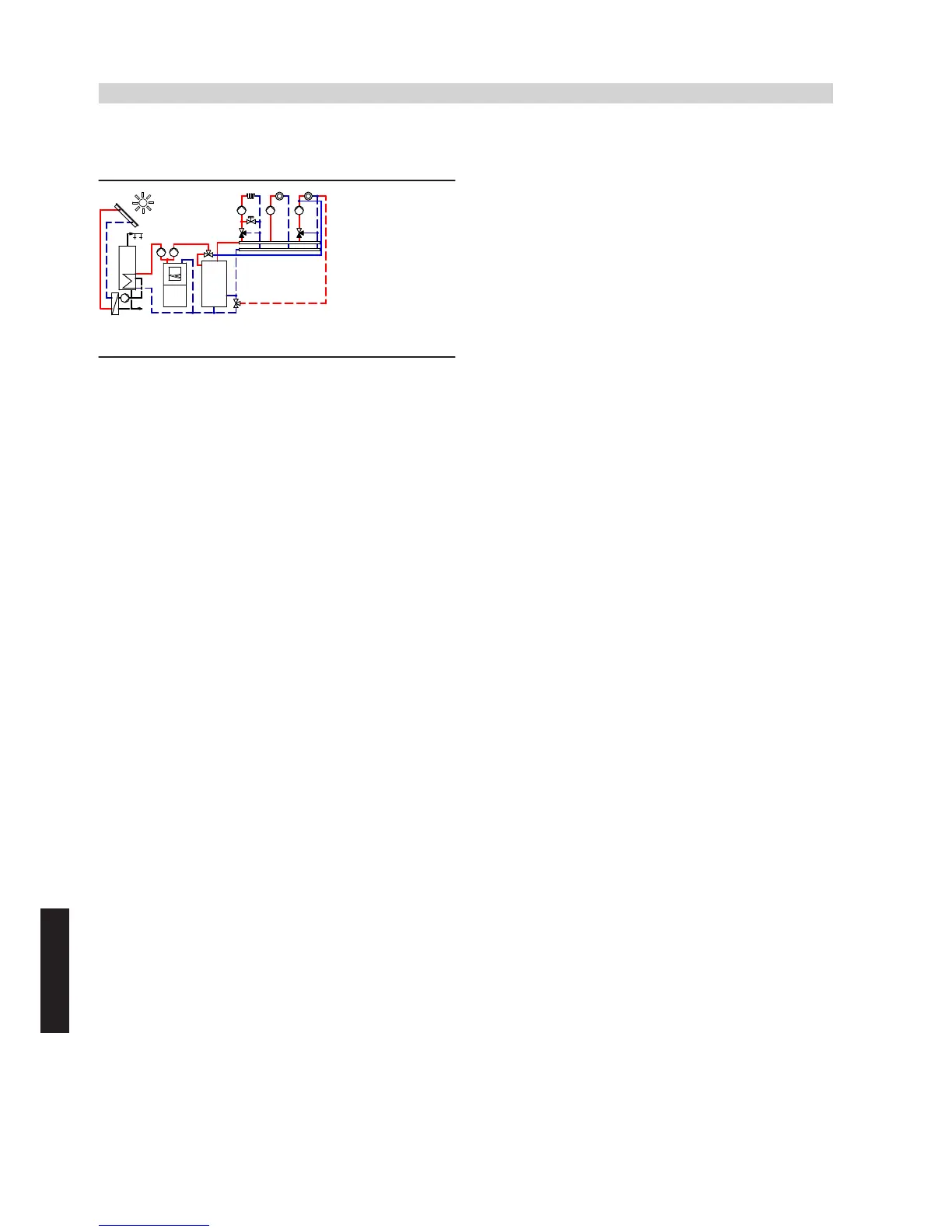
7.4 Vitocal 300-A, one heating circuit without mixer, two heating circuits with mixer, DHW
heating (as option with solar), heating water buffer cylinder and active cooling
ID: 4605093_1304_05
Application range
Detached houses with cooling demand, with up to three heating cir-
cuits with different utilisation patterns; size the DHW cylinder in accord-
ance with current standards and prevailing requirements.
Main components
■ Vitocal 300-A, type AWCI or AWO, with Vitotronic 200, type WO1B
■ Heating circuit distributor with one heating circuit without mixer and
two heating circuits with mixer
■ Vitocell 100-V DHW cylinder, type CVW, 390 litres
■ Heating water buffer cylinder
Heating water buffer cylinder
The minimum flow rate of the heat pump is safeguarded via heating
water buffer cylinder
zP
and secondary pump
6
. It is possible to use
differential pressure-dependent heating circuit pumps
uZ
,
oZ
and
q-
Z
.
Note
In type AWCI, circulation pump for cylinder heating
5
is replaced by
an internal and fully wired 3-way diverter valve.
In cooling mode, safeguard the minimum flow rate in the secondary
circuit. Open valves on the heating circuit distributor fully and perma-
nently or install an overflow valve.
Central heating by heat pump
Heat pump
1
starts when the actual temperature captured by tem-
perature sensor
zQ
of heating water buffer cylinder
zP
falls below the
set temperature selected at control unit
2
.
Heat pump
1
supplies the heating circuits with heat. Control unit
2
of heat pump
1
regulates the heating water flow temperature and
thereby the heating circuits. The secondary pump
6
delivers the
heating water either to heating water buffer cylinder
zP
or to DHW
cylinder
eP
. Heating circuit pumps
uZ
,
oZ
and
q-Z
deliver the required
water volume to the heating circuits. The heating circuit flow rate is
regulated by opening and closing the thermostatic radiator valves or
the underfloor distributor valves and/or through an external heating
circuit control unit. Heat pump
1
and secondary pump
6
are
switched off once the actual return temperature at the return temper-
ature sensor exceeds the temperature set at the control unit.
Any heat not absorbed by the heating circuits is stored in heating water
buffer cylinder
zP
. This achieves a long runtime for the heat pump.
Heat pump 1 restarts when the actual temperature at buffer temper-
ature sensor
zQ
of heating water buffer cylinder
zP
falls below the set
value. The heat pump stops again when the set temperature at the
heat pump return is reached.
During the power-OFF period, the heating circuits will be supplied with
heat from heating water buffer cylinder
zP
.
DHW heating by heat pump
In the delivered condition, DHW heating by heat pump
1
is given
priority over the heating circuit and takes precedence at night.
The heat demand is issued via cylinder temperature sensor
eQ
and
control unit
2
, which controls circulation pump for cylinder heating
5
in conjunction with secondary pump
6
. The control unit raises the
flow temperature to the value required for DHW heating.
DHW reheating can be provided by an electric booster heater (e.g.
immersion heater inside the DHW cylinder or instantaneous heating
water heater
4
in the flow). The control unit switches 3-way diverter
valve/pump
5
to the heating circuit when the actual temperature at
cylinder temperature sensor
eQ
exceeds the set value selected at the
control unit.
Instantaneous heating water heater (accessories)
The flow temperature can be raised with instantaneous heating water
heater
4
(accessories). This serves to cover peak loads, e.g. when
drying buildings or screed, or in mono energetic systems.
Solar DHW heating (option)
Heat pump control unit
2
in Vitocal 300-A can be connected via KM
BUS distributor
8
to a Vitosolic 100 (type SD1)
rU
to achieve solar
DHW heating.
Circulation pump
rE
in Solar-Divicon
rW
starts and DHW cylinder
eP
is heated up when the temperature differential between collector
temperature sensor
rR
and cylinder temperature sensor
eW
exceeds
the set value.
The heat pump will be locked out against cylinder heating when the
temperature at cylinder temperature sensor
eQ
in the DHW cylinder
exceeds the set value selected at the control unit.
The solar thermal system heats the cylinder to the set value selected
at solar control unit
rU
.
Active cooling function
The active cooling function is enabled by control unit
2
as soon as
the threshold value for the cooling limit temperature that can be selec-
ted at the control unit is exceeded. Heat pump
1
and secondary pump
6
start, heating/cooling 3-way diverter valves
iU
and
iI
are switched
to cooling. Reversing the refrigerant circuit generates cold water that
is transported into heating circuit
uP
. The dew point for the area heat-
ing system is monitored by contact humidistat
iE
.
Note
All lines where the cold water temperature can fall below the dew point
should be insulated so that they are vapour diffusion-proof.
In cooling mode, safeguard the minimum flow rate in the secondary
circuit. Open valves on the heating circuit distributor fully and perma-
nently or install an overflow valve.
Vitocal 300-A/350-A
(cont.)
214
VIESMANN
System examples
7
5822 472 GB

 Loading...


