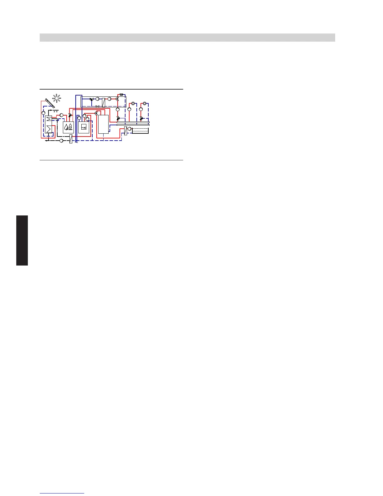
4.4 Vitocal 300-G/350-G with one heating circuit without mixer, two heating circuits with
mixer, DHW heating with solar backup, heating water buffer cylinder, external heat source
(dual mode parallel operation), natural cooling function via NC-Box (with mixer), and
swimming pool
ID: 4605352_1304_03
Application range
Detached houses and apartment buildings with swimming pool, with
up to three different heating circuits and cooling demand. Size DHW
cylinder
eP
in accordance with current standards and requirements.
Main components
■ Vitocal 300-G/350-G, type BW or BWC, up to 17 kW
■ Vitotronic 200, type WO1B
■ DHW cylinder
■ Heating water buffer cylinder
■ NC-Box
■ External heat source with Vitotronic 200, type KO1B, KO2B, KW6B
■ Solar thermal system for DHW heating
■ Swimming pool
Heating water buffer cylinder
The minimum flow rate of heat pump
1
is safeguarded via heating
water buffer cylinder
tP
and secondary pump
6
. It is possible to use
differential pressure-dependent heating circuit pumps
zU
,
iE
and
oZ
.
Central heating by heat pump
Heat pump
1
and secondary pump
6
start when the actual tem-
perature captured by temperature sensor
tQ
of heating water buffer
cylinder
tP
falls below the set temperature selected at control unit
2
.
Heat pump
1
supplies the heating circuit with heat. Control unit
2
regulates the heating water flow temperature and thereby the heating
circuit. Secondary pump
6
delivers the heating water to heating water
buffer cylinder
tP
. The heat pump with primary pump
5
and secon-
dary pump
6
is stopped when the set temperature at the integral
return temperature sensor is reached. Heating circuit pumps
zU
,
iE
and
oZ
deliver the required water volume to the heating circuits.
To balance the difference in energy between the primary and secon-
dary circuits, operate heating water buffer cylinder
tP
in parallel to the
heating circuits. Any heat not absorbed by the heating circuits is stored
in heating water buffer cylinder
tP
. In addition, heat pump
1
achieves
long runtimes.
During the power-OFF period, the heating circuits will be supplied with
heat from heating water buffer cylinder
tP
.
DHW heating by heat pump
In the delivered condition, DHW heating by heat pump
1
is given
priority over the heating circuit and should ideally take place during the
night.
The heat demand is issued via upper cylinder temperature sensor
eQ
and control unit
2
, which controls the circulation pump for cylinder
heating
7
, cylinder loading pump
eZ
and motorised 2-way valve
eE
.
Heat pump
1
raises the flow temperature to the value required for
DHW heating.
The cylinder temperature can be raised above 60 °C with external heat
source
wP
.
DHW heating with solar backup
Control unit
2
can be connected via KM BUS distributor
qQ
to a
Vitosolic 100, type SD1
rQ
to achieve DHW heating with solar
backup.
Circulation pump in Solar-Divicon
rP
starts and DHW cylinder
eP
is
heated up when the temperature differential between collector tem-
perature sensor
rW
and cylinder temperature sensor
rR
exceeds the
set value.
The solar thermal system heats the cylinder to the set value selected
in the Vitosolic 100, type SD1
rQ
.
Central heating with an external heat source
A demand signal is issued to external heat source
wP
if the heat pump
cannot maintain the required flow temperature (captured by flow tem-
perature sensor
wE
) and if the outside temperature is lower than the
dual mode temperature of the external heat source. The external heat
source starts; mixer
wW
initially remains closed towards the heating
circuit. Mixer
wW
opens towards the heating circuit only when the
required flow temperature has been reached at boiler water tempera-
ture sensor
wU
. Mixer
wW
closes towards the heating circuit when the
required flow temperature has been achieved. External heat source
wP
is shut down when the flow temperature (captured by
wE
), with
mixer
wW
closed towards the heating circuit, no longer falls below an
adjustable threshold for a given period (i.e. there is either no longer
any heat demand or heat pump
1
is supplying adequate heat).
Note
The system example is only applicable in conjunction with modulating
boilers without lower temperature limit.
Match the heating curve of the external heat source to the heating
curve of the heating circuit with the highest flow temperature. Depend-
ing on the system scope and layout, we recommend that these are
offset upwards in parallel.
Natural cooling function
The building can be cooled with heat pump control unit
2
in conjunc-
tion with NC-Box
uP
(accessories). The natural cooling function is
enabled by control unit
2
as soon as the outside or room temperature
(cooling limit temperature) that can be selected at control unit
2
is
exceeded. Circulation pumps
uQ
and
uW
in NC-Box
uP
start and 3-
way diverter valve
zI
switches to cooling. Heat is now extracted from
the room via underfloor heating circuit
zP
and transferred to the brine
circuit via the plate heat exchanger in NC-Box
uP
. The brine circuit
transfers the heat to the ground. DHW can be heated by heat
pump
1
whilst cooling mode is operational.
Swimming pool heating
Swimming pool heating is produced hydraulically via the changeover
of 3-way diverter valve
q-R
. If the temperature falls below the value
set at the thermostat for swimming pool temperature control
q-Q
, a
demand signal is sent to control unit
2
.
In the delivered condition, the swimming pool heating is supplied with
priority 3. In the selected priority, DHW heating is operated with priority
1 and central heating with priority 2. The swimming pool water is
heated to the set value selected at the thermostat for swimming pool
temperature control
q-Q
.
Vitocal 300-G/350-G
(cont.)
86
VIESMANN
System examples
4
5822 472 GB
 Loading...


