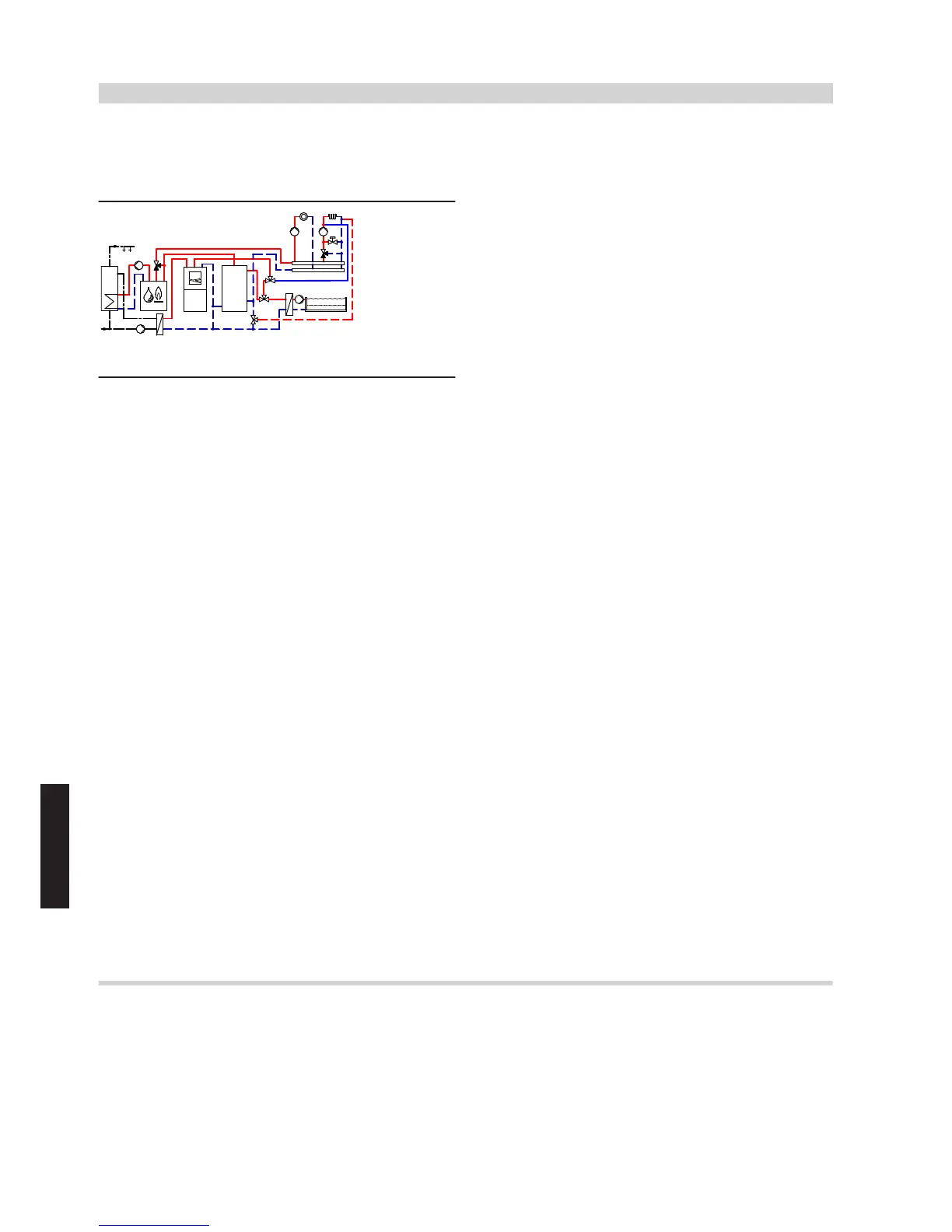
6.3 Vitocal 200-A, one heating circuit without mixer, one heating circuit with mixer and
active cooling function, DHW heating, heating water buffer cylinder, external heat source
(dual mode operation) and swimming pool
ID: 4605507_1304_02
Application range
Detached and two-family houses with swimming pool, cooling demand
and two heating circuits with different user patterns. Size the DHW
cylinder in accordance with current standards and requirements.
Main components
■ Vitocal 200-A with Vitotronic 200, type WO1C
■ Heating circuit distributor with one heating circuit without mixer and
one heating/cooling circuit with mixer, controlled via KM BUS
■ DHW cylinder, external heat exchanger (cylinder loading system)
■ Heating water buffer cylinder
■ External heat source with Vitotronic 200, types KO1B, KO2B or
KW6B
■ Swimming pool
■ Active cooling function
Heating water buffer cylinder
The minimum flow rate of the heat pump is safeguarded via heating
water buffer cylinder
zP
and secondary pump
6
. It is possible to use
differential pressure-dependent heating circuit pumps
uZ
and
oZ
.
Central heating by heat pump
Heat pump
1
starts when the actual temperature captured by buffer
temperature sensor
zQ
of heating water buffer cylinder
zP
falls below
the set temperature selected at the control unit.
Heat pump
1
supplies the heating circuits with heat. Heat pump con-
trol unit
2
regulates the heating water flow temperature and thereby
the heating circuits. Secondary pump
6
delivers the heating water
either to heating water buffer cylinder
zP
or to DHW cylinder
eP
. Heat-
ing circuit pumps
oZ
and
uZ
deliver the required water volume to the
heating circuits. The flow rate in the heating circuit is regulated by
opening or closing the thermostatic radiator valves or the valves of the
underfloor heating distributor.
The heat not absorbed by the heating circuits is stored in heating water
buffer cylinder
zP
. The inverter controlled compressor adjusts its out-
put accordingly to achieve a long heat pump runtime.
Heat pump
1
and secondary pump
6
are switched off once the
actual flow temperature at flow temperature sensor
7
in the secon-
dary circuit exceeds the temperature set at the control unit.
Heat pump 1 restarts when the actual temperature at buffer temper-
ature sensor
zQ
falls below the set value. The heat pump stops again
when the set flow temperature is reached.
During the power-OFF period the heating circuits are supplied with
heat from heating water buffer cylinder
zP
.
DHW heating
In the delivered condition, DHW heating by heat pump
1
is given
priority over the heating circuits and takes place from 00:00 to
24:00 h.
The heat demand is issued via cylinder temperature sensor
eQ
and
control unit
2
, which controls 3-way diverter valve
5
in conjunction
with secondary pump
6
and cylinder loading pump
eE
. Control unit
2
raises the flow temperature to the value required for DHW heat-
ing.
Cylinder temperatures of up to 60 °C can be achieved via external heat
source
tP
or instantaneous heating water heater
4
.
Central heating with an external heat source
Depending on the system configuration, additional high limit safety cut-
outs may be needed to protect the heat pump against high tempera-
tures (preventing excessive system pressure). This should be checked
for each system individually.
A demand signal is issued to start external heat source
tP
if the heat
pump cannot maintain the required flow temperature (captured by sys-
tem flow temperature sensor
zW
of external heat source
tP
). Mixer
tR
initially remains closed towards the heating circuit. Mixer
tR
opens
from the external heat source towards the heating circuit and regulates
to the required set flow temperature, only when the required minimum
flow temperature has been reached at boiler water temperature sensor
tE
of the external heat source. Mixer
tR
closes from the external heat
source towards the heating circuit when the required flow temperature
has been achieved.
External heat source
tP
stops if mixer
tR
is closed towards the heating
circuit and the flow temperature (captured at system flow temperature
sensor
zW
) does not fall below an adjustable threshold value for a
specified time. There then is either no heat demand or heat pump
1
is delivering sufficient heat.
Swimming pool heating
Swimming pool heating is activated hydraulically via the changeover
of 3-way diverter valve
qYT
. If the temperature falls below the set value
at swimming pool temperature controller
qYQ
, a demand signal is sent
to control unit
2
via EA1 extension
qYR
.
In the delivered condition, swimming pool heating has priority 3. The
higher set priorities are DHW heating (with priority 1) and central heat-
ing (with priority 2). If no higher priorities are present, 3-way diverter
valve
qYT
changes over to swimming pool heating, and the swimming
pool water is heated until the set value at swimming pool temperature
controller
qYQ
is reached.
Active cooling function
Active cooling function 2 is enabled if the value for the cooling limit
temperature that can be adjusted at control unit
2
is exceeded at
outside temperature sensor
3
. Heat pump
1
and secondary pump
6
are started. The 3-way diverter valves "Heating/cooling"
iO
are
switched to cooling. By reversing the refrigerant circuit, cooled heating
water is transported to cooling circuit
uP
.
The set flow temperature is controlled via flow temperature sensor
uE
and control unit
2
. Contact humidistat
iE
ensures that no con-
densation and therefore damage can occur as a result of low temper-
atures.
Note
All lines where the coolant temperature can fall below the dew point
should be insulated so that they are vapour diffusion-proof.
In cooling mode, safeguard the minimum flow rate in the secondary
circuit.
To do so, use suitable valves on the heating circuit distributor. See
Vitoset pricelist.
Vitocal 200-A
(cont.)
194
VIESMANN
System examples
6
5822 472 GB


 To Next Page
 Loading...