7
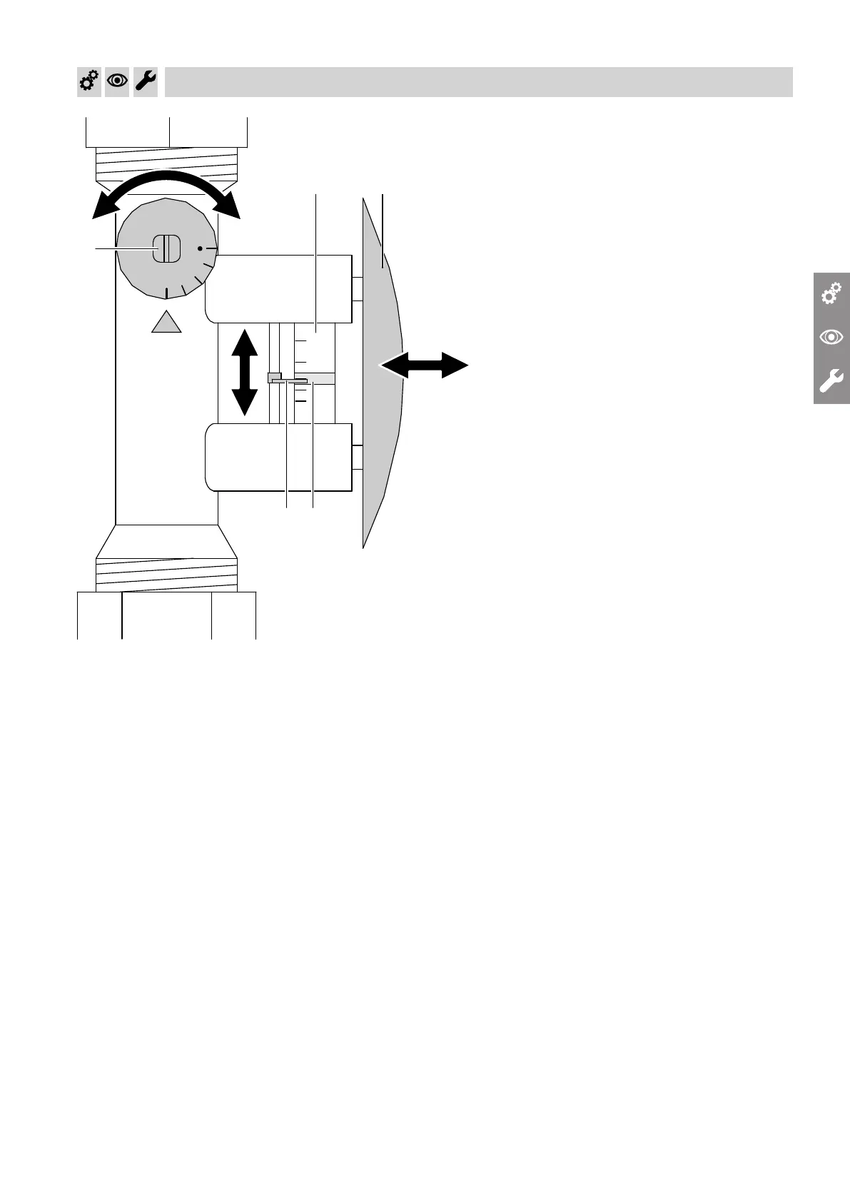
Fig.1
1.
Set sliding marker
A
on scale
B
to the flow rate
determined from the diagram below.
2.
Push in bracket
C
.
3.
Turn adjusting disc
D
anti-clockwise as far as it will
go to position "D".
4. Reduce the pump speed on the DHW side until the
bottom edge of indicator band
E
is at or above
sliding marker
A
.
5.
Only if indicator band
E
is still above sliding
marker
A
: Turn adjusting disc
D
clockwise until
the bottom edge of indicator band
E
drops down to
the sliding marker.
6.
Pull out bracket
C
. This keeps the window clean
for subsequent checking.
Commissioning, inspection, maintenance
Setting the heating output (cont.)
5549 892 GB
 Loading...