Gasifying boiler Vigas
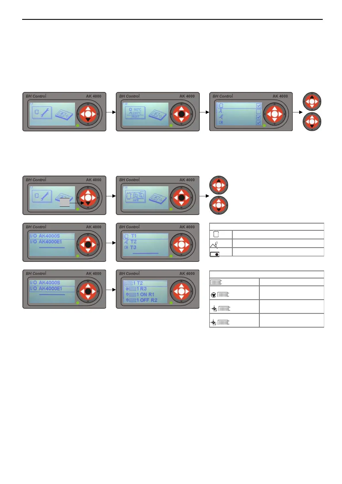
13.5 DISPLAY LINE
13.6 ELECTRIC CONNECTION - INPUTS AND OUTPUTS OF CONTROL SYSTEM AK4000
I/O AK4000S – connection to power board
T1
Boiler thermometer T1
T2
Exhaust gas thermometer T2
T3
Indoor thermostat T3
I/O AK4000E1 – connection for Expander 1
1 T2
Thermometer UK1 to T2
1 R3
Pump voltage UK1 to
R3
1 ON R1
Phase servo-unit
„OPEN“ to R1
1 OFF R2
Phase servo-unit
„CLOSE“ on R2
22
Display allows to indicated particular information about control system unit AK4000. By pressing ▲
choose required data and press „ENTER“. Marked data will be displayed in information line (chap.3.5).
Control system AK4000 enables to display each input and output according to actual configuration of the
boiler for particular contacts.
2x
Press „ENTER“ button
and using ▲ buttons
choose required modul.