Gasifying boiler Vigas
3. DESCRIPTION OF AK4000 CONTROL
3.1 SAFETY INSTRUCTIONS
Please check the cover panels protection before you plug-in the line connector
Avoid any contact of line connector with boiler hot parts (e.g. smoke flue).
Make sure, that upper isolation under the panel remains dry ( risk of short circuit)
Do not stress the line connector.
Always disconnect the line connector when a new electrical components are being connected to the
boiler (e.i. indoor room thermostat, discharge fan, circulation pump)
Do not remove protection (cover panels) when boiler in operating process, especially not fan cover
panel.
Check if voltage displayed on the label is same as your distribution network.
Always keep to the terms of use.
3.2 CONNECTION TO THE POWER SUPPLY
Control AK 4000 is integral part of VIGAS boilers.
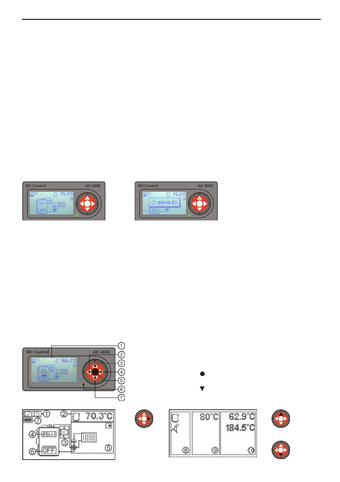
Control is connected when line connector is plugged into the power supply 220/230V. Display with basic
image is active when connector line is plugged-in (pic.4). Servo-flap used in VIGAS
Lambda Control
is set to
basic position (pic.5).
3.3 SERVICE CONDITIONS
Control AK4000 is designed for operation temperature area from +5 up to +45 C. Control can not be used
in moisty environment or direct sunlight.
3.4 MAINTENANCE AK4000 CONTROL
Keep in clean and dust free environment. Antistatic or wet wipes are recommended to wipe-off dust and
impurities from metal covers and control panel.
3.5 CONTROL PANEL
The part of this electronic control is panel equipped with buttons, pictograms and display. Further
information will be available in the next steps of this manual. The operating system of each button is
compound and it depends on the text description on display and particular boiler configuration set up by
manufacturer.
1. Graphic display 128 x 64 pix.
2. Button ◄ with functions, ENTER
3. Button▲ with functions
4. Button ► with functions, EXIT (ESC)
5. Button (ENTER) with functions
6. LED control (green - OK, red - ERROR)
7. Button switch functions