2/9
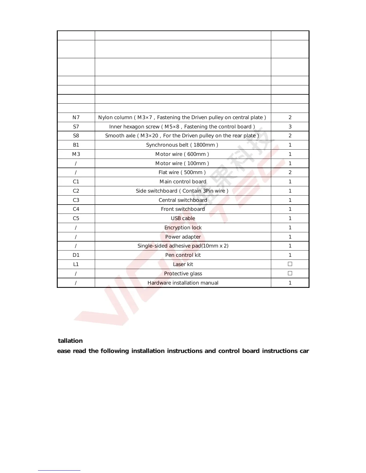
Serial N Parts Quantity
S4 Set screw(M5,Fastening the acrylic front plate, rear plate and
synchronous belt)
4
N4 Nut column(M5×6,Fastening the acrylic central plate, flat pulley and
pen control kit/Laser kit)
18
S5 Inner hexagon screw(M3×35,Fastening the Driven pulley) 2
S6 Inner hexagon screw(M3×10,Fastening the Stepper motor) 8
N5 Nut(M3,Fastening the Driven pulley on central plate) 2
N6 Nylon column(M3×5,Fastening the Driven pulley on central plate)
2
S7 Inner hexagon screw(M5×8,Fastening the control board) 3
S8 Smooth axle(M3×20,For the Driven pulley on the rear plate) 2
B1 Synchronous belt(1800mm) 1
M3 Motor wire(600mm) 1
/ Motor wire(100mm) 1
/ Flat wire(500mm) 2
C1 Main control board 1
C2 Side switchboard(Contain 3Pin wire) 1
C3 Central switchboard 1
C4 Front switchboard 1
C5 USB cable 1
/ Encryption lock 1
/ Power adapter 1
/ Single-sided adhesive pad(10mm x 2) 1
D1 Pen control kit 1
L1 Laser kit
□
/ Protective glass
□
/ Hardware installation manual 1
2.Installation
Please read the following installation instructions and control board instructions carefully,
and pay attention to the sequence of installation. The shape of parts in the following installation
instructions is only as a sigh. Please refer to the shape of the actual parts purchased. Please pay
attention to the clearance between the pulley and the profile in center part, and also it should be
able to slide smoothly in both directions. Please pay attention to the position of the synchronous
wheels on the stepper motors.
2.1 Installation instructions
 Loading...