TECHNICAL DATA
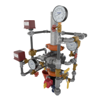
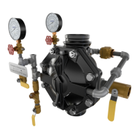
2” MODEL G-2000 DRY VALVE
RISER ASSEMBLY
Page 7 of 13
The Viking Corporation, 210 N Industrial Park Drive, Hastings MI 49058
Telephone: 269-945-9501 Technical Services: 877-384-5464 Fax: 269-818-1680 Email: techsvcs@vikingcorp.com
Visit the Viking website for the latest edition of this technical data page www.vikinggroupinc.com.
Form No. F_011110 17.04.27 Rev 17.1
I. INSPECTION
Weekly inspection is recommended. If the system is equipped with a low air (or nitrogen) alarm, monthly inspections may be adequate.
1. Check pressure gauges located on the supply side and system side of the dry valve. Verify that the proper ratio of air (or
nitrogen) pressure to water supply pressure is being maintained. Refer to Table 1.
2. Verify that the intermediate chamber of the dry valve is free of water. No water should flow from the drip check when the
plunger is pushed.
3. Verify that there is no air coming out of the 1/2” outlet of the PORV.
4. If equipped with a Viking Model E-1 Accelerator:
a. Check the air pressure gauge located on the top of the accelerator. Air pressure in the upper chamber of the accelerator
should equal the pneumatic pressure maintained in the system.
5. Verify that the water supply main control valve is open and all trim valves are in their normal operating position.
6. Check for signs of mechanical damage and/or corrosive activity. If detected, perform maintenance as required or, if necessary,
replace the device.
7. Verify that dry valve and trim are adequately heated and protected from freezing and physical damage.
II. TESTS
Quarterly Tests
A. Water Flow Alarm Test
Quarterly testing of water ow alarms is recommended and may be required by the Authority Having Jurisdiction.
1. Notify the Authority Having Jurisdiction and those in the area affected by the test.
2. To test the local electric alarm and/or mechanical water motor gong (if provided), OPEN the alarm test valve in the dry valve
trim.
a. Electric alarm pressure switches (if provided) should activate.
b. Electric local alarms should be audible.
c. The local water motor gong should be audible.
d. Verify that remote station alarm signals (if provided) were received.
3. When testing is complete, close the alarm test valve.
4. Verify:
a. All local alarms stop sounding and alarm panels (if provided) reset.
b. All remote station alarms reset.
c. All supply piping to water motor properly drains.
5. Verify that the alarm test valve is CLOSED.
6. Verify that the intermediate chamber of the dry valve is free of water. No water should flow from the drip check when the
plunger is pushed.
7. Notify the Authority Having Jurisdiction and those in the affected area that testing is complete.
B. Main Drain Test
Quarterly performance of the Main Drain Test is recommended and may be required by Authorities Having Jurisdiction to verify integrity
of the water supply.
1. Notify the Authority Having Jurisdiction and those in the area affected by the test.
2. Record pressure reading from the water supply pressure gauge.
3. Verify that the intermediate chamber of the dry valve is free of water. No water should flow from the drip check when the
plunger is pushed.
4. Verify that there is no air coming out of the 1/2” outlet of the PORV.
5. Verify that the dry pipe system is pressurized at or above the minimum pressure recommended in Table 2 for the water supply
pressure available.
6. Fully OPEN the main drain valve located on the base of the dry valve.
7. When a full flow is developed from the main drain, record the residual pressure from the water supply pressure gauge.
8. When the test is complete, SLOWLY CLOSE the main drain.
9. Compare test results with previous flow information. If deterioration of the water supply is detected, take appropriate steps to
restore adequate water supply.
10. Verify that normal water supply pressure and system pneumatic pressure have been restored, and that all alarm devices and
valves are secured in normal operating position.
11. Notify the Authority Having Jurisdiction that the test is complete. Record and/or provide notification of test results as required
by the Authority Having Jurisdiction.
C. Low Air Alarm Test
Quarterly testing of low air alarms is recommended.
1. Notify the Authority Having Jurisdiction and those in the area affected by the test.
2. Close the water supply main control valve supplying the dry valve.
 Loading...