PROCEDURA DI CONFIGURAZIONE MANUALE DEI PARAMETRI
L’ordine delle configurazioni raffigurate nel diagramma della sequenza
manuale è:
• Regolazione tempo di inserzione serratura
• Regolazione tempo di conversazione, autoaccensione, risposta.
• Rimappatura tasti (P1 e P2).
• Reset EEPROM (cancellazione delle configurazioni impostate e ritorno
ai dati di Default).
NOTA: la regolazione del tempo di conversazione, autoaccensione, ris-
posta avviene in un’unica operazione.
Esempio: se il trimmer viene posizionato su 3, il valore assunto sarà per
conversazione = 50, autoaccensione = 8, risposta = 12 secondi.
MANUAL PARAMETER CONFIGURATION PROCEDURE
The order of the configurations shown in the manual sequence diagram is:
• Lock activation time adjustment
• Talk, self-start, response time adjustment.
• Button remapping (P1 and P2).
• EEPROM reset (clearing the set configurations and returning to the
default data).
NOTE: Adjusting the talk, self-start and response time takes place in a
single step.
For example, if the trimmer is set to 3, the value taken on will be talk =
50, self-start = 8, response = 12 seconds.
COMANDO
COMMAND
TEMPO CONFIGURABILE DA TRIMMER “TEMPO ATTIVAZIONI” ATTRAVERSO 16 POSIZIONI (tempo espresso in secondi)
PROGRAMMABLE TIME THROUGH 16 POSITIONS TRIMMER “ACTIVATION TIME” (time in seconds)
POSIZIONE
POSITION
1 2 3 4 5 6 7 8 9 10 11 12 13 14 15 16
Serratura
Lock
1 2 4 6 8 10 12 14 16 18 20 22 24 26 28 30
Conversazione
Talk
30 40 50 60 70 80 90 100 110 120 130 140 150 160 170 180
Accensione
Switch-on
5 6 8 10 11 13 15 16 18 20 21 23 25 26 28 30
Risposta
Response
7 10 12 15 17 20 22 25 27 30 32 35 37 40 42 45
FUNZIONAMENTO
• I tasti P1 o P2 inviano le chiamate verso i posti interni che alla risposta
della chiamata andrà in comunicazione audio o audio/video dipenden-
temente dal tipo di unità elettronica (13F1/13F2) o dal tipo di posto
interno (citofono o videocitofono).
• Nel caso in cui in un impianto siano installate più un’unità elettroniche
e da una di queste viene inviata una chiamata, qualora vi sia già in co-
municazione un’altra unità elettronica con un posto interno, nell’unità
elettronica che invia la chiamata verrà emesso un tono di occupato.
NOTA:
P1 invia di default la chiamata al posto interno identificato con ID = 1
P2 invia di default la chiamata al posto interno identificato con ID = 2
tab. 2
La sequenza della configurazione manuale è rappresentata nel diagramma a pagina 6.
The manual configuration sequence is shown in the diagram on page 7.
OPERATION
• Buttons P1 or P2 send calls to the indoor stations that when the call is
answered will go into audio or audio/video communication depending
on the type of electronic unit (13F1/13F2) or the type of indoor station
(interphone or monitor).
• If multiple electronic units have been installed in a system and a call
is sent from one of these, if there is already another electronic unit
communicating with an indoor station, the electronic unit sending the
call will emit a busy tone.
NOTE:
P1 by default sends the call to the indoor station identified with ID = 1
P2 by default sends the call to the indoor station identified with ID = 2
NERO/BLACK
BLU/BLUE
ROSSO/RED
P1
P2
CONNETTORE COLLEGAMENTO PULSANTE P2
CONNECTOR BUTTON P2
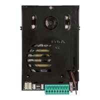
Figure 7 shows the connection to make between the
electronic unit and button P2 housed in the printed
circuit board which is located in cover plate 13K1 to-
gether with the 3-conductor wiring.
g. 7
In gura 7 è indicato il collegamento da realizzare tra
unità elettronica e pulsante P2 alloggiato nel circuito
stampato che si trova nella placca 13K1 unitamente
al cablaggio a 3 conduttori.
5
13F1 - 13F2