27
EN
*
BUS TERMINATION
This note applies to all devices with Due Fili Plus technology equipped with “BUS termination connector or dip-switch”, which is identi
-
ed by the screen-printed letters “ABC” and marked on the wiring diagrams with
*
.
For correct adaptation of the line, make the setting according to the following rule:
Maintain position “A” if the BUS enters and exits from the device;
Move to position “B” (if Elvox cable) or to position “C” (if CAT5 twisted pair cable) if the BUS line terminates in the device itself.
“A” = NO TERMINATION
“B” = TERMINATION 100 ohm
“C” = TERMINATION 50 ohm
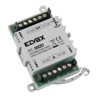
INSTALLATIONS WITH PASSIVE DISTRIBUTOR 692D
(DIN rail version)
ALWAYS use output 1 on distributor type 692D (the only one that has no termination jumper).
For termination of type 692D: If outputs “OUT”, “2”, “3” or “4” are not used, KEEP the jumper on the “TOUT”, “T2”, “T3” or “T4” connec-
tor. The default “TOUT” connector is in the “100” position (Elvox cable), position it to “50” only if using a CAT5 twisted pair cable.
INSTALLATIONS WITH ACTIVE DISTRIBUTOR 692D/2.
The termination jumper must be positioned on “B” (for Elvox cable) or on “C” (for CAT5 twisted pair cable) IF AND ONLY IF the BUS
terminates at the device itself. It must be left on “A” if effecting entry-exit using terminals 1-2 on 692D/2.
Minimum conductor section
Terminals Ø up to 10m
Electric lock 1,5 mm
2
Others: -, +U, +I, -L (#) 1 mm
2
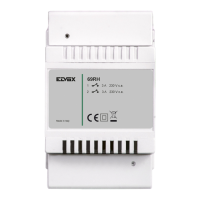
# Additional power supply units (type 6923, 6582, 6982) must be installed as near as possible to the device to which they
are connected.
Legenda for wiring diagram