13
7549/M
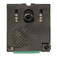
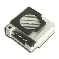
1 - Connecteur USB pour la programmation à partir du logiciel
2 - Bornier de connexion
1, 2 = Ligne numérique BUS
FP * = Appel palier (référence à la borne M).
Après avoir procédé à sa conguration via SaveProg, il est
possible de l'utiliser comme entrée pour la fonction « Alerte
». Consulter le paragraphe correspondant dans le manuel
d'installation et d'utilisation.
Remarque : les deux bornes FP/M peuvent également être
utilisées, lorsque la fonction « Alerte » n'est pas activée,
pour simuler un appel provenant de l’Art. 6120 et destiné
au poste principal par rapport aux éventuels postes
intérieurs secondaires.
M * = Masse
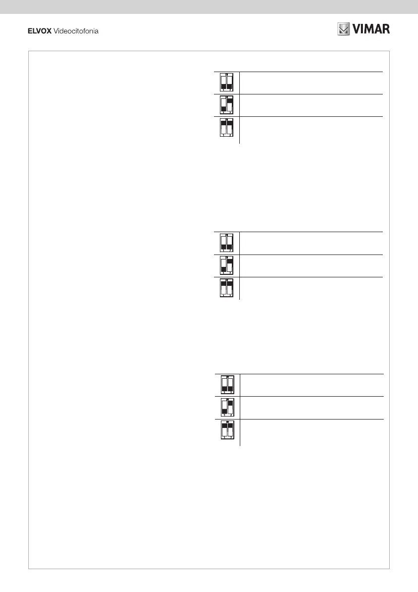
3 - Dip-Switch de conguration (Terminaison Bus)
Remarque : * la distance maximale des connexions aux bornes
correspond à 10 m.
TABLEAU SWITCH
A = Le câble du BUS arrive aux bornes 1, 2 et continue vers
un autre poste intérieur
B = Le câble BUS avec une impédance caractéristique de
100 ohms (câble Elvox 732I ou 732H) arrive aux bornes 1,
2 et la colonne montante s'arrête au poste intérieur
C = Le câble BUS ayant une impédance caractéristique de
50 ohms (câble cat. 5 ou cat. 6 à paires torsadées) arrive
aux bornes 1, 2 et la colonne montante s'arrête au poste
intérieur
1 - USB connector for programming using software
2 - Connection terminal block
1, 2 = Digital BUS line
FP * = Local Landing Call (reference to terminal M).
When congured using SaveProg, this input can be used
for the “Alert” function. See the relevant paragraph in the
use and installation manual.
Note: the FP/M pair of terminals can also be used, when
use as “Alert” is not active, to simulate a call from Art. 6120
intended for the master with respect to any of its secondary
indoor stations.
M * = Earth
3 - Conguration dip switch (Bus termination)
Note: * the maximum connection distance to the terminals is
10 m.
SWITCH TABLE
A = the BUS cable enters terminals 1, 2 and continues to
another indoor station
B = The BUS cable with a characteristic impedance of 100
Ohms (Elvox 732I or 732H cable) enters terminals 1, 2 and
the riser stops in the indoor station.
C = The BUS cable with characteristic impedance of 50
Ohms (Cat. 5 or Cat. 6 twisted pair cable) enters terminals
1, 2 and the riser stops in the indoor station.
1 - USB-Anschluss für Programmierung über die Software
SaveProg
2 - Anschlussklemmenleiste
1, 2 = Digitale Busleitung
FP * = Lokaler Etagenruf (Signal an Klemme M)
Kann mittels Konguration über SaveProg als Eingang
für die Funktion "Warnmeldung" verwendet werden.
Siehe entsprechenden Abschnitt in der Installations- und
Bedienungsanleitung.
Hinweis: Das Klemmenpaar FP/M kann bei nicht aktivierter
Funktion "Warnmeldung" auch dazu verwendet werden,
einen von Art. 6120 an das Gruppen-Hauptgerät
gerichteten Ruf gegenüber seinen etwaigen sekundären
Innenstellen zu simulieren.
M * = Masse
3 - Dip-Schalter für Konguration (Bus-Abschluss)
Hinweis: * die maximale Anschlusslänge an die Klemmen
beträgt 10 m.
SCHALTERTABELLE
A = Das BUS-Kabel tritt in die Klemmen 1, 2 ein und führt
und zu einer anderen Innenstelle weiter
B = Das BUS-Kabel mit typischer Impedanz 100 Ohm
(Elvox Kabel 732I oder 732H) tritt in die Klemmen 1, 2 ein
und die Steigleitung endet an der Innenstelle
C = Das BUS-Kabel mit typischer Impedanz 50 Ohm (Kabel
Cat.5 oder Cat.6 mit gepaarten Doppeladern) tritt in
die Klemmen 1, 2 ein und die Steigleitung endet an der
Innenstelle

 Loading...