Do you have a question about the Vimpex Hydrosense HSCP and is the answer not in the manual?
Instructions for securely fixing the control panel to a suitable surface at eye height.
Procedure for safely removing and refitting the control panel's front fascia for access.
Explanation of the labels and functions for each terminal on the circuit board.
Details on fault, local alarm, and main alarm relay operations.
Description of normal, alarm, and fault conditions, including LED indicators.
Procedures for disabling zones and sounders, and their functions.
Indication of a mains power failure and troubleshooting steps.
Troubleshooting battery connection and charging circuit faults.
Details on CPU, power, earth, sounder, and communication faults.
Steps for correctly installing Hydrowire cable and connection boxes.
Procedure for connecting Hydrowire to the main control panel terminals.
How to connect a remote lamp indicator to the Hydrowire system.
Methods for testing the Hydrowire system after installation.
Important points to check for Hydrowire installation and operation.
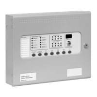
The Hydrosense HSCP is a conventional water detection control panel designed for use with the Hydrowire system and Hydrosense probes. It is available in 2, 4, and 8 zone configurations, offering a comprehensive solution for monitoring and signaling water detection events. The panel includes an integral, mains-powered battery charger and power supply, ensuring continuous operation even during power outages. It also features voltage-free relay contacts for both general alarm and local alarm conditions, which activate upon water detection, allowing for local control and signaling to other systems.
The control panel's fascia incorporates standard silence and reset controls, along with two seven-segment LED displays and MODE, SELECT, and ENTER buttons. These controls facilitate easy entry and storage of codes for configuring the panel to meet specific installation requirements.
Under normal operating conditions, only the green "Power On" LED is illuminated. When a water detector activates, the "Common Alarm" indicator lights up, and the zonal "Alarm" indicators flash at approximately 2Hz. Both the alarm and local alarm relays will operate, signaling connected systems. Any sounders connected to the circuits will activate in common, zonal, or two-stage mode, depending on the selected configuration options.
To silence sounders, the "Enable Control" key must be inserted, and the "Silence/Sound alarm" button pressed. Once silenced, the "Zone Alarm" LEDs will change from flashing to a steady state. Pressing the "Silence/Sound alarm" button again will reactivate the sounders, allowing them to be toggled on and off as needed. To reset the panel, the "Enable Control" key is inserted, and the "Reset" button is pressed.
In the event of a zone fault, such as the removal of a water detector or wiring issue, the "Fault" LED and corresponding "Zone Fault" LEDs will illuminate. Similarly, a fault in the sounder circuit wiring will cause the "Fault" and "Sounder Fault" LEDs to light up. A power fault, indicated by the "Fault" and "Power Fault" LEDs, signifies a mains power failure, battery disconnection, or a high impedance in the charging circuit. The "System Fault" LED will light if the configuration memory is not set or becomes corrupt.
All LED indicators can be tested by pressing the "Lamp Test" button, without needing the "Enable Control" key. The buzzer can also be silenced at any time by pressing the "Buzzer Silence" button.
The system allows for the disablement of specific parts, which can be useful during maintenance or when works in a building might trigger false alarms. To disable zones, the "Enable Control" key is inserted, and the "Mode" button is pressed until "d" appears on the LED display. The "Select" button is then used to choose the zone number, and "Enter" confirms the disablement. The "Disable" LED and the "Zone Fault" LED for the disabled zone will light. Sounder outputs can be disabled by pressing the "Mode" button to select "db" on the display, then pressing "Enter," which will illuminate the "Disable" and "Sounder Fault" LEDs.
Delays can be activated on zones as configured in options 31 to 48. Pressing the "Mode" button until "Ad" appears on the display, then "Enter," will apply the set alarm output delays to the designated zones. The fault relay can also be disabled via configuration option 22.
The Hydrosense HSCP panels feature a single-handed test mode. With the "Enable Control" key inserted, pressing the "Mode" button until "t" appears, then selecting the desired zone with the "Select" button and confirming with "Enter," will activate test mode. In this mode, water detector activations are automatically reset after a few seconds (once the detector dries), eliminating the need to return to the control panel for resets. Disablements and zone tests are cleared by repeating the selection sequence, which toggles the function on or off.
Configuration options, accessible at access level 3, allow for customization of the panel's operation. To access this level, the "Write Enable" switch (located behind the panel plate) must be slid to the right. The panel buzzer will "pip" three times every few seconds as an indication of access level 3. Configuration codes are entered using the "Mode" and "Select" buttons for tens and units, respectively, and confirmed with "Enter." A flashing dot on the units display indicates a set option. Previously set options can be reviewed by scrolling through the codes; those with a flashing dot are active.
The Hydrosense HSCP control panels require minimal specific maintenance. If the panel becomes dirty, it can be wiped with a damp, lint-free cloth and then dried. Detergents or solvents should not be used, and care must be taken to prevent water from entering the enclosure.
The control panel contains sealed lead-acid batteries for standby power during mains failures. These batteries typically have a life expectancy of about four years and should be tested annually according to the manufacturer's recommendations to ensure their continued suitability for standby applications.
Routine testing of the Hydrosense Water Detection System helps identify any malfunctions of the control panel, which should be reported to the alarm maintenance company immediately. If the control panel becomes faulty, the complete electronic assembly can be replaced. Before replacement, any configured options should be noted, and both mains and battery power must be removed. Field wiring should be carefully labeled and disconnected from the terminals. The PCB can then be removed by undoing the two screws holding the plate in position. Installation of a new PCB is the reverse of this procedure.
Internal indicators are provided for troubleshooting fault conditions not detailed on the front panel. These include:
The panel's power supply requires a 230V AC supply, connected to a fused terminal block containing a 20mm, F1.6A L250V fuse, which should only be replaced with a similar type. The output voltage is 28V DC +/- 2V, with a total current rating of 3 Amps, including a maximum of 0.7A for battery charging. Fuse F12 on the circuit board is a self-resetting electronic fuse rated at 4 Amps. Mains wiring should be routed at least 50mm away from other low-voltage wiring and securely bonded to the building earth. Battery leads are supplied wired to the PCB, with a link to connect the two batteries in series. The PCB is fitted with a 20mm, 3.15A T1 glass fuse (F13) in the battery charging circuit, which must only be replaced with the same type. Correct battery polarity is crucial to prevent damage to the control panel.
A zone designation label is provided for writing text descriptions of each zone, facilitating easier identification of abnormal conditions.
For Hydrowire commissioning, lengths should be laid on the floor in protected areas, with no more than 2 meters between Hydrowires. For localized protection, distances may be greater. The cable should remain in contact with the floor, possibly using P clips. While sturdy, the cable can be damaged by crushing or excessive bending; a bend radius of 150mm is recommended. The Hydrowire must be terminated with an end-of-line plug (K2110). The terminating connection box (K2106) should be secured to the wall or floor to prevent stretching or pulling of the Hydrowire. The installed Hydrowire system should include a K2106 connection box, Hydrowire cable (K2104 or/and K2105), and an end-of-line plug unit (K2110). A red warning label should be clearly visible. Hydrowire should not contact surfaces above 70°C, and lengths greater than 50 meters are not allowed.
For connection to the control panel, the + and - terminals inside the connection box must be connected to the Z+ and Z terminals at the control panel. End-of-line resistors at the control panel should be discarded. It is advisable to leave the connection box lid off until all testing is complete.
A K2103 remote lamp unit can be wired to the - and rem. terminals in the K2106 connection box to identify the water detection area, especially in floor voids. Only one remote lamp unit should be connected per connection box.
Testing of Hydrowire is best done by dipping a thumb and forefinger into tap water, shaking off excess drips, and gripping the Hydrowire firmly while rolling it slowly. This should produce an immediate indication at the control panel. Over-wetting should be avoided to prevent long drying times.
General Hydrowire checklist points include avoiding excessive wetting, observing polarity, keeping lengths short to minimize electrical noise, avoiding installation near other cables, not twisting, bending sharply, stretching, standing on, or crushing the Hydrowire, avoiding exposure to surface temperatures above 70°C, and using only recommended Hydrowire system components.
Hydrosense Probe commissioning is best achieved by dipping the probe pins into a cup of tap water. This should immediately trigger a reaction at the control panel, the LED on top of the probe, and any fitted remote lamp unit or sounder.
| Type | Control Panel |
|---|---|
| Model | HSCP |
| Enclosure Rating | IP65 |
| Weight | 2.5kg |
| Outputs | 4 relay outputs |
| Humidity Range | 0 to 95% RH, non-condensing |
| Communication | RS485 |
| Power Supply | 230V AC |
| Inputs | 8 digital inputs |