Man-1131_Hydrosense_HSCP_01 Page 8 of 18
8. Sounder circuit wiring
All sounders must be of the polarised type. If non-polarised sounders are used the control panel will
permanently show a fault condition. See table 6 on page 7 for a list of compatible sounder types.
Sounder circuits are monitored for open and short circuit faults by placing a 10K end of line monitoring
resistor across the last device on the circuit.
Sounder circuits must be wired as a single, radial circuit with no spurs or T junctions to enable the
monitoring circuit to work correctly.
A maximum of 1.6 Amps is available for powering sounders with a maximum load of 0.41 Amps on any one
circuit.
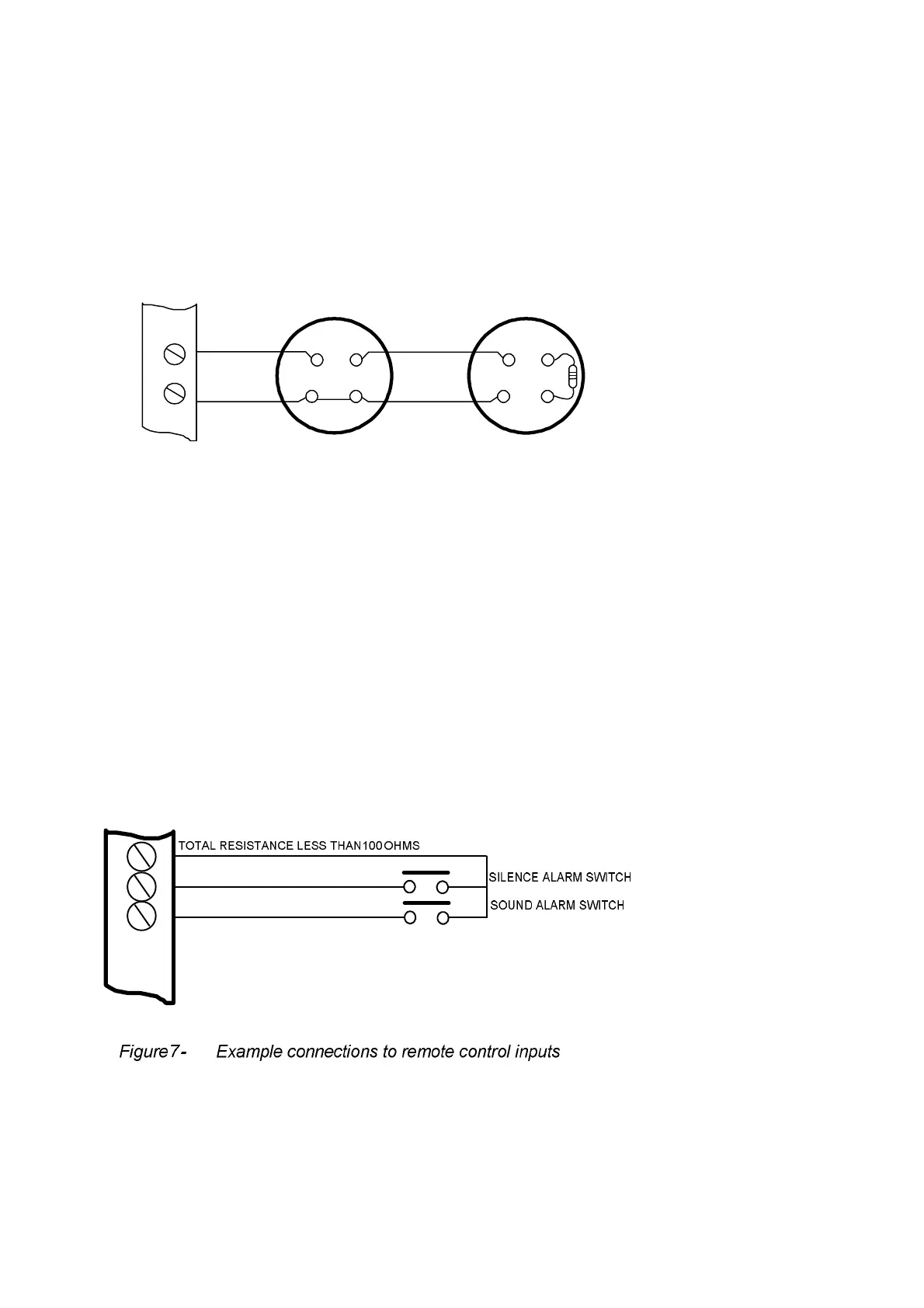
9. Connection to remote control terminals
Some functions of the control panel can be controlled externally from the panel if required.
These are abbreviated at the terminals block as follows:
a) Remote 0 V supply - ROV
b) Silence Alarm – SIL
c) Sound Alarm – AL
d) Fault – FLT
e) Reset – RST
To activate these inputs, the remote 0 Volt (R0V) supply must be connected to the input via a normally open
switch or contact and via a resistance of no greater than 100 ohms.
All of the remote control inputs are non-latching.
ROV SIL AL FLT RST
+
-
S1
Figure 6. - Sounder circuit wiring
10K end of line
resistor
POLARISED
SOUNDER
IN OUT
+
IN
+
OUT
_ _
POLARISED
SOUNDER
IN OUT
+
IN
+
OUT
_ _
www.acornfiresecurity.com
www.acornfiresecurity.com