Do you have a question about the Vingtor Stentofon VSS-V2 and is the answer not in the manual?
Explains the VSS-V2 system's role as a navigational aid for sound signals.
Lists key features like ease of use, noise cancellation, and connectivity.
Specifies the visibility distance requirement for panels.
Illustrates the system's components and connections.
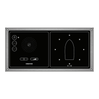
Introduces the different panel types available in the system.
Details the dimensions and appearance of the master panel.
Details the dimensions and appearance of the slave panel.
Shows dimensions and components of the microphone unit.
Identifies mandatory installation requirements for specific vessel types.
Describes interfaces for VDR, mute inputs, status, and web access.
Explains the 6-wire interface for connecting slave panels.
Details the 10-wire interface for microphone connectivity.
Provides power requirements and current load specifications.
Describes system status and direction LED relay outputs.
Explains the input for muting the system during horn activation.
Details the input for muting the system during PA broadcasts.
Emphasizes thorough reading of procedures and checking ambient noise levels.
Provides guidance on installing master, slave, and microphone units.
Advises on cable routing to prevent vibration damage.
Specifies the required clearance from compasses.
Details terminal blocks, DIP switches, and potentiometers for configuration.
Describes the terminal block for the microphone amplifier unit.
Specifies approved cable types and shielding for signal integrity.
Details proper grounding procedures for reliable system operation.
Explains DIP switch and potentiometer settings for the master panel.
Details DIP switch settings for the slave panel.
Provides a visual guide for connecting all system components.
Shows detailed dimensions and mounting views of the microphone unit.
Displays dimensions, panel cut-out, and mounting holes for the master panel.
Displays dimensions, panel cut-out, and mounting holes for the slave panel.
Emphasizes pre-delivery testing and post-installation procedures.
Checks for secure fastening of equipment and tightened cable glands.
Refers to installation procedures and highlights importance of noise reduction.
Verifies cable type, connections, and grounding as per diagrams.
Outlines the procedure for powering on and testing the master panel.
Describes the process for powering on and testing slave panels.
Explains the system's ability to indicate sound direction based on ISO 14859:2012.
Details how to set up tests using signal generators and different angles.
Lists checks for speaker output, direction, and duration after testing.
Covers operation of speaker, indicators, dimmer, and volume controls.
Describes the function of the internal speaker for horn signals.
Explains the meaning of the 8 red LEDs and the system status LED.
Details the front panel control for adjusting LED light intensity.
Describes how to adjust the audio volume using panel buttons and LEDs.
Explains the function of the squelch button for adjusting the threshold level.
Details the override button for direct audio from the microphone.
Describes accessing and using the system's web interface for status and configuration.
Access for authorized personnel to configure signal processing.
Details how to configure network settings for the web interface.
Introduces the reverse LED indication mode available via firmware.
Explains how DIP switch S1 activates the reverse LED function.
Illustrates how the reverse function works with examples.
Shows the standard LED indication mode.
Displays reversed LED indication for double-ended ferries.
Shows reversed LED indication with added vessel sticker.
Addresses flashing fault LEDs, possibly due to power or connection issues.
Helps diagnose incorrect direction readings from the system.
Explains causes for a flashing green status diode, like override or DSP issues.
Suggests checking DIP switch settings for backlight issues.
Guides checking override and speaker connections for no sound issues.
Discusses why the system might not detect certain signal types like pure tones.
Addresses issues with incorrect direction indications, possibly due to placement or reflections.
Advises on cleaning precautions and periodic system checks.
Lists item numbers and descriptions for replacement PCBs and microphone kits.
Lists dimensions, mounting, IP rating, voltage, audio specs, LEDs, and buttons.
Lists dimensions, power source, mounting, IP rating, voltage, LEDs, and buttons.
Lists dimensions, housing, IP rating, environment, and microphone count.
| Brand | Vingtor Stentofon |
|---|---|
| Model | VSS-V2 |
| Category | Car Navigation system |
| Language | English |