EasyManua.ls Logo

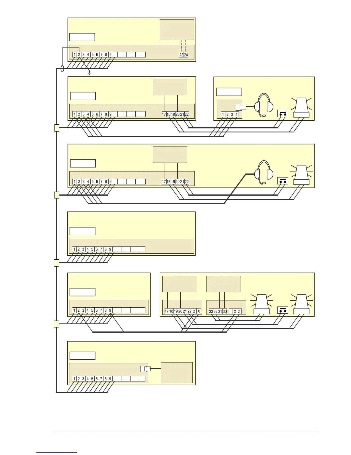
Vingtor VSP-211-L - Figure 3: Cabling Diagram Based on System Configuration Example

Default Icon
20 pages
Print Icon
To Next Page IconTo Next Page
To Previous Page IconTo Previous Page
Loading...
9
VSP 12 Way Batteryless Telephone System
Technical Manual
A100K10873
Figure 3: Cabling diagram based on system conguration example
WHEELHOUSE
ENGINE ROOM
EHS-24
EHS-24
EHS-24
EHS-220
VSP-36-PELP
VSP-36-PELP
STEERING GEAR
CAPTAIN’S CABIN
OPEN DECK
CORRIDOR
Ext. no. 1
Ext. no. 2
Ext. no. 4
Ext. no. 6
Ext. no. 5
Ext. no. 3
Ext. no. 2
24 VDC
+
_
CD-4
10 11 12 13 14 15 16
10 11 12 13 14 15 16
10 11 12 13 14 15 16
10 11 12 13 14 15 16
10 11 12 13 14 15 16
+
+
+
_
_
_
VSP-223-L
VSP-223-L
Ext.
Alarm
stop
Ext.
Alarm
stop
Ext.
Alarm
stop
10 11 12 13 14 15 16
Alternative power
for common
battery use
VSP-211-L
24 VDC
24 VDC
24 VDC
220 VAC
+
+
+
_
_
_
External Power
External Power
External Power
External Power
VSP-213-L + VSPK
VSP-213-L + VSPK IRR-24 IRR-220
VSP-122P
CD-16
E
x
t
.
n
o.
ENGINE CONTROL ROOM
CHIEF ENGINEER CABIN