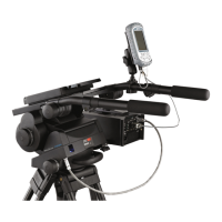
The Vinten Vector 750i Encoded Head (V4080-0001) is an encoded pantographic pan and tilt head designed for professional broadcast and film camera operators, particularly suited for VR/AR tracking applications. It provides precise positioning data and ensures stable and accurate placement of virtual graphics in live environments when partnered with the Virtual Reality Interface (VRi) box.
Function Description
The Vector 750i features a unique linkage counterbalancing (pantograph) mechanism and thin film (TF) drag assemblies for smooth pan and tilt motions. It also incorporates a unique slide plate and balance mechanism position measurement for mid-broadcast camera adjustments. The head processes positional tracking data from optical encoders on the tilt and pan axes, and from lenses with encoder outputs, to provide a single data stream to graphics rendering systems via the devicelink.i interface cable. In addition to tracking pan and tilt angles, it monitors balance and camera slide plate position, allowing adjustments without recalibrating tracking.
Important Technical Specifications
- Maximum payload: 75 kg (165.3 lbs)
- Payload Centre of Gravity height range: 80–250 mm (3–10 in.)
- Weight (complete with pan bar and wedge adaptor): 17.9 kg (39.5 lbs)
- Height (with wedge adaptor):
- Minimum balance setting: 234 mm (19.2 in.)
- Maximum balance setting: 304 mm (11.9 in.)
- Length (without pan bar): 354 mm (13.9 in.)
- Width (without pan bar): 352 mm (14.1 in.)
- Tilt range @ 75 Kg (16.3 lb): ±52°
- Pan range: 360°
- Pan resolution: 1,800,000 counts/360°
- Tilt resolution: 1,643,000 counts/360°
- Counterbalance: Fully variable with digital readout
- Operational temperature range: -40°C to 60°C (-40°F to 140°F)
- Battery type (for level bubble illumination): PP3 (9V)
- Level bubble illumination: 15 seconds
- Encoder power requirements: 5VDC
- Base fixing: Standard 4 bolt and Quickfix groove
Usage Features
The head is designed for ease of use and precise control.
- Perfect Balance: The balance system is easily adjusted using the Perfect Balance adjustment knob [21] to compensate for differing payload Centre of Gravity (C of G) heights. This knob is a multi-turn control, and tilting the platform slightly can facilitate turning it.
- Thin Film (TF) Drag: Both pan and tilt mechanisms feature TF drag systems for smooth camera movement. Pan and tilt drag adjustment knobs ([10], [13]) are located on the left-hand side of the head, allowing adjustment from 0 (minimum drag) to 9 (maximum drag). The whip-pan facility is unaffected by the pan drag setting.
- Brakes: Friction brakes on each axis ([3], [4]) allow the head to be locked at any chosen position. They are operated by levers at the right-hand rear of the head. A tilt axis centre lock [22] on the right-hand side secures the camera mount platform [17] horizontally for transport or payload changes. WARNING: Brakes should only be used to secure the payload when the camera system is not in use, and must be set to the OFF position for transportation and storage. They should not be used to increase drag.
- Illuminated Level Bubble: A level bubble [8] at the rear of the head has a time-delay illumination unit operated by a button [7]. Pressing the button illuminates the level bubble and drag adjustment knobs for 15 seconds. The battery for this unit is located in the base of the head.
- Pan Bars: Pan bar mounting points ([12], [25]) are at the rear of the head. The supplied telescopic pan bar attaches with a pan bar clamp [24] and offers angular adjustment. Optional fixed, short pan bars are available, and a second pan bar can be fitted for hand controls.
- Camera Mounting: The camera attaches via a wedge adaptor (Part No. 3460-3). It is crucial to ensure the wedge adaptor is fully engaged and locked, indicated by a green band above the operating lever [27].
- Balancing the Head: Proper balancing is essential for correct operation. This involves positioning the payload fore and aft so its C of G is above the platform pivot, and then adjusting the counterbalance for the payload C of G height. All pan bars and camera accessories must be fitted in their operational position before balancing. WARNING: Increase the balance setting for a heavy out-of-balance payload BEFORE disengaging the centre lock to prevent violent platform tipping.
- Digital Display: A digital numeric display [1] and push button [2] allow operators to view the current counterbalance setting (one press) or camera slide plate position (two presses). The balance and camera slide plate LEDs [6] indicate the displayed setting.
- VRi Box Mounting: The VRi box can be mounted to either side of the head using mounting points [11] and a bracket. It is important to fit the VRi box before balancing the head; if fitted afterward, rebalancing is required.
Maintenance Features
Routine maintenance is limited, focusing on checking the platform slide clamp effectiveness and level bubble illumination.
- Cleaning: Regular cleaning involves wiping with a lint-free cloth. Accumulated dirt can be removed with a vacuum cleaner, paying attention to the wedge location faces. CAUTION: Do not use solvent- or oil-based cleaners, abrasives, or wire brushes, as these can damage protective surfaces. Only detergent-based cleaners should be used for mechanical surfaces. For outdoor use in adverse conditions, the head should be covered when not in use, and salt spray should be washed off with fresh water.
- Cleaning Balance Mechanism Tracks: Built-in wipers automatically clean the balance mechanism tracks, but in adverse conditions, manual cleaning may be required.
- Vertical Tracks: Requires removing the platform [17] by unscrewing it from the balance mechanism [31]. The tracks [32] can then be cleaned with an isopropanol-based cleaner and a pipe cleaner.
- Horizontal Tracks: No dismantling is necessary. After removing the payload and setting the balance mechanism to maximum, tilt the platform fully backward and apply the tilt brake [4]. Pulling down the flap guard [35] reveals the bevel gear [33], allowing access to the horizontal tracks [34] through the holes in the bevel gear for cleaning.
- Level Bubble Illumination Unit Battery Replacement: The PP3 (9V) battery [37] should be replaced yearly or when illumination is inadequate. Access is gained by removing the battery compartment coverplate [39] from the underside of the head. After replacement, both the balance and slide plate sensors will need calibrating.
- Adjustments:
- Platform Slide Clamp Adjustment: If the clamp [18] does not properly secure or release the slide, it can be adjusted by removing a plastic cap [18.2] to access a slotted shaft [18.1], slackening the clamp screw [18.3], turning the slotted shaft, and retightening.
- Repositioning the Wedge Adaptor: If horizontal balance cannot be achieved, the wedge adaptor [26] can be repositioned on the slide plate [17] by removing four securing screws [28]. WARNING: Use only the provided M6 x 30 mm screws to avoid preventing slide plate operation.
- Pan and Tilt Brake Adjustment: Brakes should be adjusted so they begin to apply after approximately one-third of the lever travel. The tilt brake is adjusted via a grub screw [4.1] accessed through a hole in the tilt unit cover. The pan brake is adjusted by turning a pin [3.3], which requires removing the payload, the head from its mounting, and the battery housing coverplate.
- Balance and Slide Plate Calibration: After a battery change or prolonged use, both the balance and slide plate sensors may need calibration. This is done by simultaneously pressing and holding the level bubble illumination button [7] and the numeric display button [2] for 2 seconds to enter calibration mode. Then, move the slide plate and Perfect Balance adjustment knob [21] to their mechanical extremes in both directions. The controller stores the maximum and minimum values. To complete, press and hold the display button [2] for 2 seconds. Calibration limits are only stored if sufficient movement is detected on the sensor; otherwise, calibration is aborted.