-5-
INSTALLATION
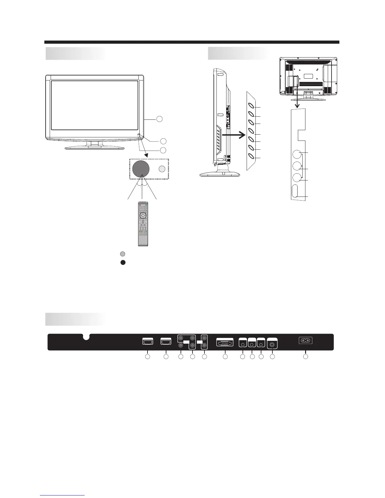
Front panel
REAR AV PASTER
1: Remote control sensor.
2: Indicator LED: GREEN POWER ON.
RED STANDBY.
3: Key board
1.SOURCE:Display the input source menu.
2.MENU:Display main MENU.
3.CH+/CH-:In TV mode,press“CH+”or“CH-”to
change the channel up and down.In MENU mode, press
“CH+”or“CH-”to select items .In standby mode,
press“CH+”or“CH-”to turn on the TV.
4.VOL+/VOL-:Adjust sound level.In MENU mode,
press“VOL+”or“VOL-”to adjust the item that you
selected.
5. STANDBY : Press this button to turn the unit ON
from STANDBY mode. Press it again to turn the set
back to STANDBY.
6.VIDEO INPUT
7.AUDIO INPUT-L
8.AUDIO INPUT-R
9.HDMI3 INPUT
10.USB INPUT
Side panel
SOURCE
MENU
CH+
CH-
VOL+
VOL-
STANDBY
1 2 3
4 5 6
7 8 9 0
+
CH
_
+
_
VOL
30 30
3
1
2
HDMI3 INPU T
VIDE O
L
R
AV2
USB
R
L
VIDEO
HDMI3 INPUT
Note: 1.Composite video input and component video input share the audio input.
2. When DVI connector is used on HDMI 1 Input, use “PC Audio” for the audio signal input.
3. When DVI connector is used on HDMI 2 Input, Use “YPbPr Audio” for the audio signal input.
HDM I1 I NPUT HDM I2 INPU T
AC IN PUT
100 -240V ~50/6 0Hz
L
R
AV1
Pr
Y
Pb
HEADPHONE
PC AUD IO
INP UT
COA XIAL
RF IN PUT
Y Pb Pr
INP UT
AUD IO
INP UT
VGA IN PUT
1 2
3
4 5
6
7
8
9
10 11
7.Headphone Output
8.PC Audio Input
9.Coaxial
10.Antenna Socket
11.AC Power Socket
1.HDMI1 Input
2.HDMI2 Input
3.Composite Video Input
4.Component Video (YPbPr) Input
5.Audio Input
6.VGA Port (PC Input)
 Loading...