Manual VIPA System 200V Chapter 2 Analog input modules
HB97E - SM-AIO - Rev. 12/32 2-29
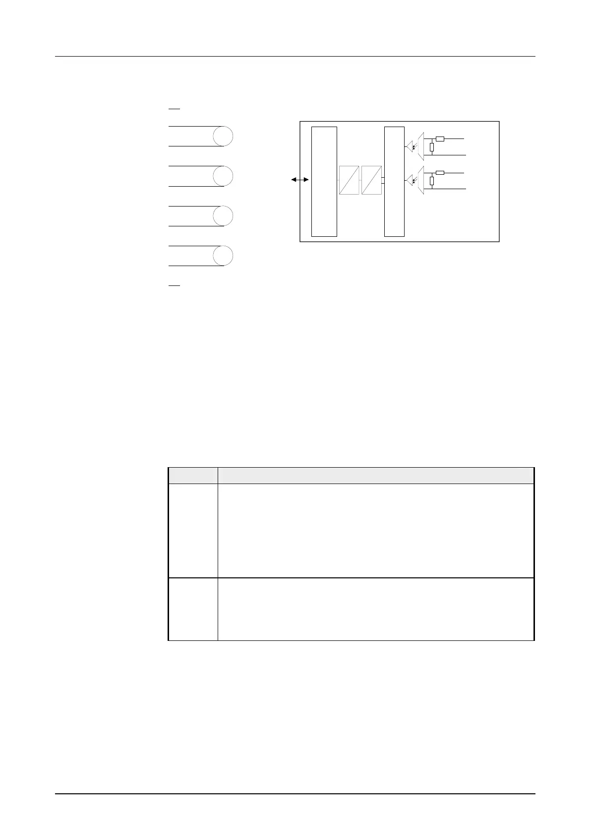
Wiring diagram Schematic diagram
1
2
3
4
5
6
7
8
9
10
A
A
A
A
-Bus
Input
Channel 0
+0
M0
Channel 1
+1
M0
.
.
.
µP
Mux
D
A
The wire break recognition is always active. In case of a wire break res.
when no encoder is connected, the LED of the according channel is turned
on. The module has no diagnostic ability.
Input data in Siemens S5 format is stored in a word. The word contains the
binary measured value with sign and information bits:
Numeric notation:
Byte Bit 7 ... Bit 0
0
Bit 0: Overflow bit (O)
0: value within measuring range
1: measuring range exceeded
Bit 1: Error bit (E: set at internal error)
Bit 2: Activity bit (A: always 0)
Bit 7 ... 3: binary measured value (see table below)
1
Bit 6 ... 0: binary measured value (see table below)
Bit 7: sign
0 positive
1 negative
Wiring and
schematic
diagram
Wire break
recognition
Numeric notation
S5 format
 Loading...