Manual VIPA System 200V Chapter 2 Analog input modules
HB97E - SM-AIO - Rev. 12/32 2-33
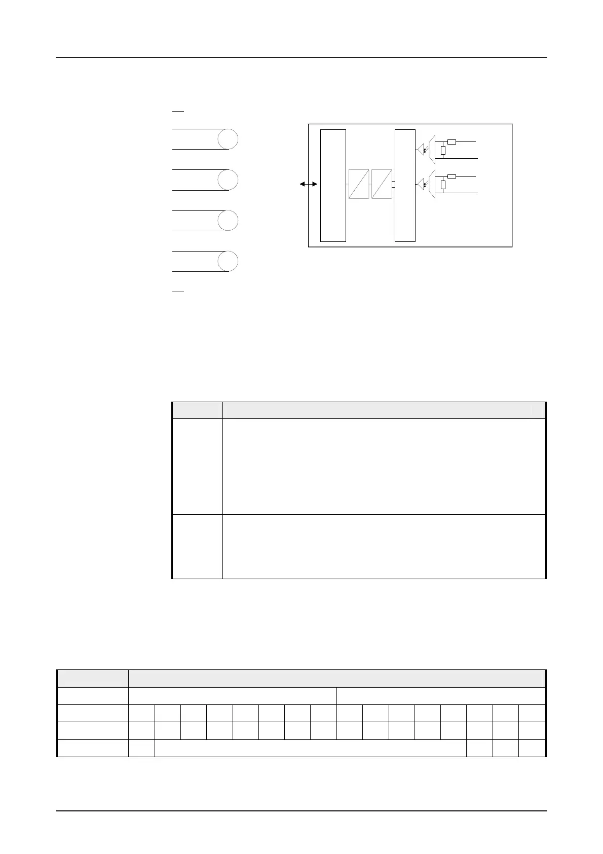
Wiring diagram Schematic diagram
1
2
3
4
5
6
7
8
9
10
V
V
V
V
-Bus
Input
Channel 0
+0
M0
Channel 1
+1
M0
.
.
.
82k
Ω
82k
Ω
1,6k
Ω
1,6kΩ
µP
Mux
D
A
Input data in Siemens S5 format is stored in a word. The word contains the
binary measured value with sign and information bits:
Numeric notation:
Byte Bit 7 ... Bit 0
0
Bit 0: Overflow bit (O)
0: value within measuring range
1: measuring range exceeded
Bit 1: Error bit (F: set at internal error)
Bit 2: Activity bit (A: always 0)
Bit 7 ... 3: binary measured value (see table below)
1
Bit 6 ... 0: binary measured value (see table below)
Bit 7: sign
0 positive
1 negative
Analog values are exclusively processed in a binary format. For this the
analog module transforms every process signal into a digital value and
transfers this as word.
Resolution Analog value
byte 1 byte 0
Bit number 15 14 13 12 11 10 9 8 7 6 5 4 3 2 1 0
Value SG 2
14
2
13
2
12
2
11
2
10
2
9
2
8
2
7
2
6
2
5
2
4
2
3
2
2
2
1
2
0
12bit + sign
SG Measuring value A E O
Wiring and
schematic
diagram
Numeric notation
S5 format
Representation of
analog values