Manual VIPA System 200V Chapter 2 Analog input modules
HB97E - SM-AIO - Rev. 12/32 2-53
During a measurement the data is stored in the data input area. The table
above shows the allocation of the data to a measured value as well as the
respective tolerance.
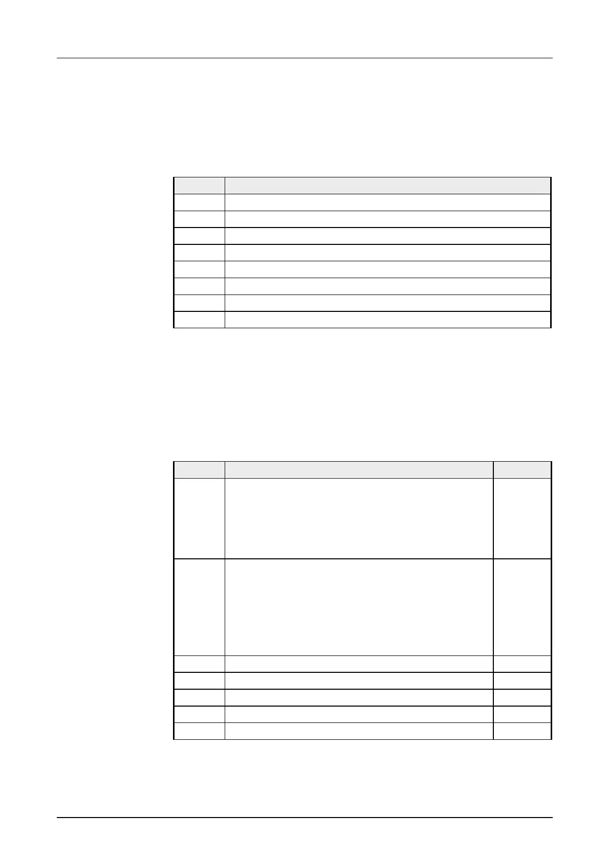
The following figures show the structure of the data input area:
Data input area:
Byte Bit 7 ... Bit 0
0 High-Byte channel 0
1 Low-Byte channel 0
2 High-Byte channel 1
3 Low-Byte channel 1
4 High-Byte channel 2
5 Low-Byte channel 2
6 High-Byte channel 3
7 Low-Byte channel 3
You may configure every channel individually. 32byte are available for the
configuration data. Configuration parameters are stored in permanent
memory and they will be retained even if power is turned off.
The following table shows the structure of the parameter area:
Parameter area:
Byte Bit 7 ... Bit 0 Default
0 Diagnostic alarm byte:
Bit 5 ... 0: reserved
Bit 6: 0: diagnostic interrupt inhibited
1: diagnostic interrupt enabled
Bit 7: reserved
00h
1 Limit value monitoring:
Bit 0: limit value monitoring channel 0
Bit 1: limit value monitoring channel 1
Bit 2: limit value monitoring channel 2
Bit 3: limit value monitoring channel 3
Bit 7 ... 4: reserved
00h
2 Function-no. channel 0 (see table) 28h
3 Function-no. channel 1 (see table) 28h
4 Function-no. channel 2 (see table) 28h
5 Function-no. channel 3 (see table) 28h
6-9 reserved 00h
continued ...
Measurement data
acquisition
Parameter data
 Loading...